
Introduction
Cleanroom contamination control depends not only on HEPA filtration, differential pressure, and room classification. It also depends on how people, materials, equipment, waste, and products move through the facility.
A technically capable HVAC system cannot fully compensate for a poorly planned workflow. When clean and unclean routes cross, doors open unnecessarily, operators retrace their steps, or incoming materials bypass controlled transfer procedures, contamination risks increase and daily operations become more difficult.
For pharmaceutical manufacturers, medical device facilities, laboratories, electronics plants, hospitals, EPC contractors, and cleanroom consultants, personnel and material flow should therefore be defined during the early design stage—not after the room layout has already been finalized.
This guide explains how to plan cleanroom personnel and material flow, how the two routes should interact, and which design details buyers and project teams should define before construction.
What Is Cleanroom Personnel and Material Flow?
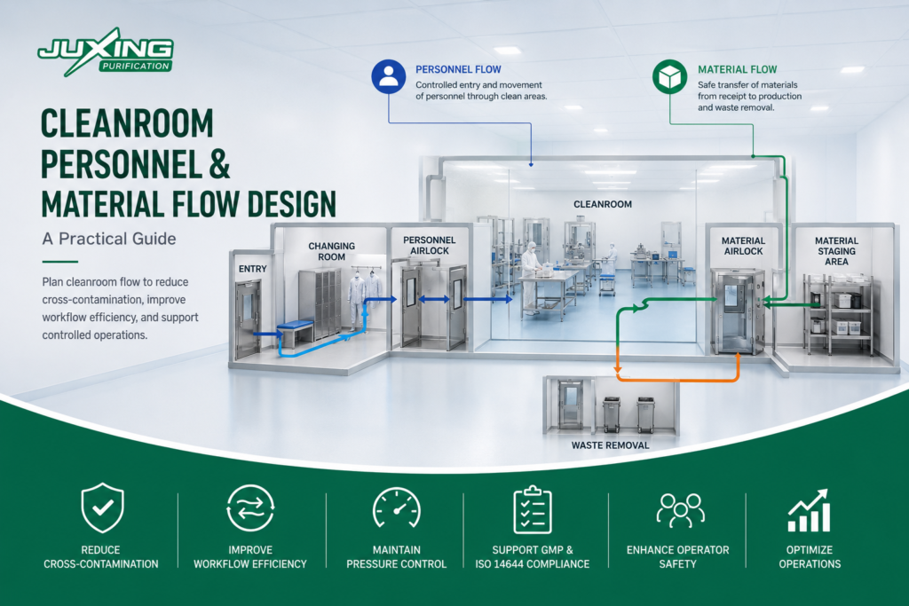
Cleanroom personnel and material flow describes the controlled movement of people and items through areas with different cleanliness levels, pressure conditions, or contamination risks.
Personnel flow may include:
- Entry into changing areas
- Gowning and hand hygiene
- Movement through personnel airlocks
- Access to production rooms
- Movement between process zones
- Exit and degowning
- Maintenance access
- Emergency evacuation
Material flow may include:
- Receipt of raw materials
- Unpacking and cleaning
- Disinfection or decontamination
- Transfer through material airlocks or pass boxes
- Movement to staging and production areas
- Transfer of finished products
- Removal of waste and used equipment
The objective is to create a logical sequence that reduces unnecessary movement and limits the possibility of contaminants travelling from less controlled areas into cleaner or more critical zones.
Why Flow Design Matters
Every movement inside a cleanroom has the potential to affect contamination control.
People release particles from skin, garments, footwear, and movement. Materials may carry dust, fibres, packaging debris, microorganisms, or residues on their external surfaces. Carts, tools, containers, and maintenance equipment can introduce additional contamination if their entry is not controlled.
Poor flow design may cause:
- Clean and dirty traffic to cross
- Operators to pass repeatedly through airlocks
- Materials to enter without adequate cleaning
- Waste to travel through incoming-material routes
- Excessive door-opening frequency
- Pressure disturbances
- Congestion in gowning or staging areas
- Higher dependence on procedural controls
- Difficulty maintaining operational discipline
EU GMP Annex 1 treats the movement of personnel and materials as part of the broader contamination control strategy. It calls for movement into and within clean areas to follow controlled and justified routes, with separate personnel and material airlocks wherever practical.
Personnel Flow and Material Flow Should Be Planned Together
Personnel and material routes should not be designed independently.
A personnel route may appear logical on an architectural drawing but create problems when combined with trolley movement, material staging, waste removal, maintenance access, or emergency escape requirements.
A coordinated flow study should consider:
- Who enters each room
- What materials enter and leave
- How frequently movement occurs
- Which doors are used
- Which cleanroom grade or ISO class is crossed
- Whether cleaning or disinfection is required
- Whether incoming and outgoing routes intersect
- Whether doors can be interlocked
- Whether pressure recovery is adequate
- How abnormal events will be handled
The objective is not necessarily to eliminate every crossing point. In many facilities, space and process constraints make complete separation difficult. The goal is to identify each interaction, evaluate its risk, and apply suitable architectural, HVAC, equipment, or procedural controls.
Start With the Process, Not the Floor Plan
One of the most common planning mistakes is designing the cleanroom layout before the production process and movement sequence are fully understood.
A better approach begins with a process-flow diagram.
The project team should map:
- Personnel entry and exit
- Raw-material receipt
- Material preparation
- Processing stages
- In-process transfer
- Finished-product removal
- Waste removal
- Cleaning-equipment movement
- Maintenance access
- Emergency routes
Only after these movements are understood should the team finalize room adjacencies, door locations, airlocks, pass boxes, corridors, and pressure zones.
ISO 14644-4:2022 covers the process for developing cleanrooms from requirements through design, construction, and start-up. It is intended for users, specifiers, designers, purchasers, suppliers, builders, and performance verifiers, reinforcing the importance of defining operational requirements before detailed execution.
Cleanroom Personnel Flow Design
Personnel are often the largest active contamination source in an occupied cleanroom. A good personnel-flow strategy should control both what operators wear and how they move.
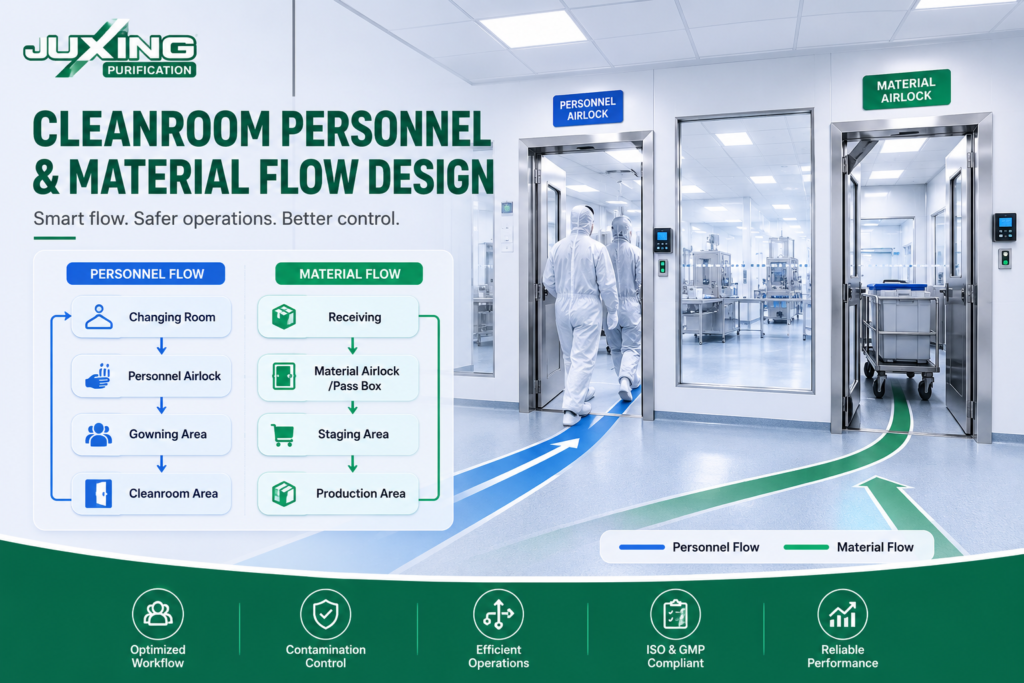
A typical entry sequence may include:
Uncontrolled Area
        ↓
Initial Changing Area
        ↓
Hand Hygiene / Preparation
        ↓
Clean Gowning Area
        ↓
Personnel Airlock
        ↓
Controlled Production Area
This sequence varies according to the application, cleanroom classification, facility risk, and applicable regulatory requirements.
A lower-risk industrial cleanroom may use a relatively simple gowning sequence. A sterile pharmaceutical facility may require multiple changing stages, defined garment sequences, and stricter separation between incoming and outgoing operators.
Gowning Rooms Are Part of the Flow System
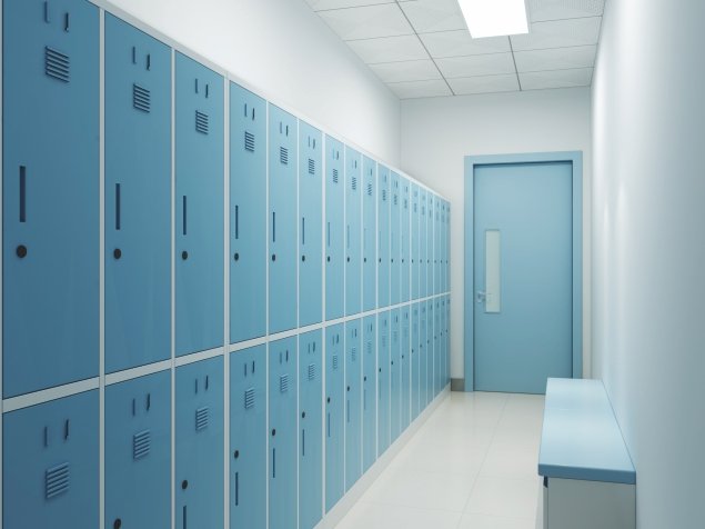
A gowning room should not be treated as an ordinary changing room.
Its layout should support a defined progression from less clean to cleaner conditions. This may involve:
- Separation of street clothing and clean garments
- Handwashing or hand sanitization
- Shoe-changing or shoe-cover procedures
- Step-over benches
- Storage for clean garments
- Mirrors for gown inspection
- Waste containers
- Clear operating instructions
- Adequate space for the expected number of operators
The physical arrangement should reduce the chance that operators touch clean garments against walls, floors, doors, benches, or previously worn clothing.
In higher-risk facilities, entry and exit may require separate routes or carefully controlled sequential procedures.
Avoid Personnel Backtracking
Personnel should move through the facility in a clear and predictable sequence.
Backtracking occurs when operators must return through a lower-control area to reach another production room, collect materials, complete records, or access support equipment.
This increases:
- Door-opening frequency
- Pressure disturbances
- Movement-related particle generation
- Procedural complexity
- Risk of entering the wrong zone
- Time spent in airlocks and corridors
Room adjacencies should therefore reflect actual work sequences.
For example, frequently connected processing stages should not be separated by a distant corridor merely because that arrangement is architecturally convenient.
Control the Number of Personnel
Cleanroom occupancy affects particle generation, heat load, airflow performance, gowning-room capacity, and operational efficiency.
The design team should establish:
- Normal occupancy
- Maximum occupancy
- Shift-change occupancy
- Maintenance occupancy
- Visitor arrangements
- Emergency conditions
The cleanroom should not be sized only for normal production if shift changes or maintenance activities regularly create congestion.
FDA guidance for aseptic processing emphasizes controlling personnel activity and limiting unnecessary access because operator presence and intervention can affect the aseptic environment.
Separate Routine and Maintenance Access Where Practical
Maintenance personnel may carry tools, spare parts, ladders, test equipment, and replacement components that do not follow the normal operator route.
Where practical, facilities should consider:
- Technical corridors
- Ceiling service access
- Rear-access equipment
- Separate maintenance entries
- Controlled tool-transfer procedures
- Defined post-maintenance cleaning and requalification
Not every facility can provide separate technical access. However, maintenance movement should still be evaluated during design rather than managed as an unexpected exception after handover.
Cleanroom Material Flow Design
Material flow begins before an item reaches the cleanroom.
The project team should understand:
- How materials arrive
- What packaging they carry
- Whether external packaging is removed
- Whether surfaces require cleaning or disinfection
- Whether materials require quarantine or status identification
- How they are transferred to production
- How empty containers and waste leave
- Whether incoming and outgoing routes are separated
A material can be chemically suitable for the process while still presenting a contamination risk through its external packaging or handling history.
Typical Incoming-Material Sequence
A controlled incoming-material route may include:
Receiving Area
      ↓
Inspection / Quarantine
      ↓
Outer Packaging Removal
      ↓
Cleaning or Disinfection
      ↓
Material Airlock or Pass Box
      ↓
Clean Staging Area
      ↓
Production Room
The precise sequence depends on the item, process, and contamination risk.
Small sealed components may be transferred through a pass box. Large equipment or pallets may require a material airlock. Heat-sensitive or sterile materials may require specialized transfer or decontamination systems.
Separate Incoming Materials From Waste
Incoming materials and outgoing waste represent very different contamination conditions.
Using the same route for both may be acceptable only when supported by a carefully controlled time separation, cleaning procedure, risk assessment, and operating discipline.
Where space permits, dedicated waste-removal routes are generally easier to control.
Potential waste streams include:
- Used garments
- Packaging waste
- Process waste
- Used tools
- Cleaning materials
- Rejected products
- Biological or hazardous waste
- Empty containers
The waste route should not compromise incoming clean materials or critical production areas.
Material Airlocks vs Pass Boxes
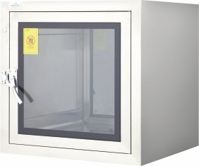
Both systems support controlled transfer, but they serve different needs.
| Feature | Material Airlock | Pass Box |
|---|---|---|
| Typical item size | Carts, trolleys, equipment, larger loads | Small or medium components |
| Personnel entry | May be possible where designed | Normally not permitted |
| Floor area | Requires a dedicated room | Integrated into a wall |
| Pressure control | Part of the room HVAC strategy | Static or actively ventilated design |
| Transfer process | May include cleaning and staging | Direct pass-through transfer |
| Main advantage | Accommodates large and complex transfers | Reduces door opening and personnel traffic |
A pass box should not be selected only because it saves space. The dimensions, loading method, cleaning access, ventilation, interlocking, and transferred items must all be considered.
Clean and Dirty Corridors
Some facilities use dedicated clean and dirty corridors to separate material and waste movement.
A clean corridor may support:
- Entry of prepared materials
- Movement of clean equipment
- Access to controlled production rooms
A dirty or return corridor may support:
- Waste removal
- Used-equipment return
- Removal of rejected materials
- Maintenance movement
This arrangement can improve separation but increases floor area, wall systems, doors, HVAC demand, and project cost.
It should therefore be selected based on process risk and operational benefit, not applied automatically to every cleanroom.
Directional or Unidirectional Flow
A directional workflow aims to move people and materials progressively through the facility without unnecessary reversal.
For example:
Receiving → Preparation → Processing → Packaging → DispatchThis can reduce crossing points and simplify contamination control.
However, “unidirectional flow” should not be interpreted as requiring every facility to have a completely one-way architectural route. In many projects, practical constraints require controlled return paths.
The important questions are:
- Where do paths intersect?
- What is the contamination state at each intersection?
- Can movements be separated by space or time?
- Is cleaning required between movements?
- Are door and pressure controls adequate?
- Are procedures realistic during peak operation?
Relationship Between Flow and Pressure Cascade
Personnel and material flow should generally progress in a manner compatible with the pressure cascade.
In product-protection facilities, cleaner or more critical rooms are commonly maintained at a higher pressure than adjacent lower-control spaces. Movement toward these areas therefore passes through progressively controlled zones.
In containment applications, pressure relationships may be reversed to prevent hazardous substances from escaping.
The flow route and pressure strategy should be reviewed together. A route that requires frequent travel against the intended pressure cascade may create repeated disturbances and operational difficulties.
Door Location and Opening Direction
Door placement has a direct effect on workflow, airflow, congestion, and safety.
The design team should consider:
- Which side personnel approach from
- Whether operators carry materials
- Cart turning space
- Door-swing conflicts
- Airlock occupancy
- Emergency escape
- Cleaning access
- Differential pressure
- Local fire and building codes
- Interlocking requirements
There is no universal rule that every cleanroom door must open toward the higher-pressure room or toward the lower-pressure room.
Pressure may influence sealing behaviour, but door direction must also satisfy safety, egress, workflow, accessibility, hardware, and regulatory requirements. The complete project context should determine the final arrangement.
Door Interlocking and Flow Control
Interlocking is commonly used at personnel airlocks, material airlocks, and pass boxes to discourage both doors from opening simultaneously.
A well-designed interlock can support:
- Pressure stability
- Controlled entry sequence
- Reduced airflow short-circuiting
- Access control
- Status indication
- Alarm reporting
However, interlocking should not create an unsafe condition.
The system must consider:
- Emergency release
- Fire-alarm response
- Power failure
- Manual override
- Occupant entrapment
- Accessible egress
- Maintenance mode
Personnel and Material Flow During Peak Operation
A layout that works during a drawing review may fail during shift changes, batch transfers, cleaning, or maintenance.
Flow analysis should consider realistic peak scenarios, such as:
- Several operators gowning simultaneously
- Multiple trolleys waiting at a material airlock
- Incoming materials and outgoing waste at the same time
- A large equipment component being replaced
- Cleaning personnel entering at shift end
- Production records or samples moving between rooms
- Emergency evacuation
Where possible, the design team should conduct a simple operational simulation or walkthrough before construction.
This does not require advanced software. Even a marked floor plan showing people, carts, door swings, waiting positions, and timing can reveal serious layout problems.
Engineering Insight
Many cleanroom layouts are reviewed room by room: the gowning room is checked separately, the airlock separately, and the production room separately.
Operational problems usually occur between those rooms.
A gowning room may have enough floor area but still become congested because its exit door conflicts with a bench. A material airlock may be correctly pressurized but too small for the trolley and operator to turn safely. A pass box may be correctly installed but positioned far from the actual workstation, causing staff to carry materials across the room.
The most reliable approach is to review the entire movement sequence from origin to destination, including waiting, turning, cleaning, door operation, and return movement.
Common Flow-Design Mistakes
1. Mixing Personnel and Material Routes Without Assessment
Shared routes may create congestion and cross-contamination risk.
Where separation is impossible, the project should define time separation, cleaning controls, and operating priorities.
2. Treating Corridors as Storage Areas
Stored materials reduce corridor width, obstruct cleaning, complicate evacuation, and create uncontrolled staging points.
3. Undersizing Airlocks
An airlock must accommodate users, carts, door swings, and required procedures—not merely meet a minimum architectural dimension.
4. Ignoring Outgoing Flow
Design teams often focus on how clean materials enter but do not adequately plan how waste, used equipment, and rejected products leave.
5. Excessive Door Numbers
Additional doors may appear to improve access, but they increase leakage paths, interlock complexity, cleaning work, and potential operational errors.
6. Locating Pass Boxes for Architectural Convenience
A pass box should support the real transfer process. Poor placement can increase manual carrying distance and movement through critical areas.
7. Depending Entirely on Procedures
Procedures are necessary, but they should not be used to compensate for a fundamentally difficult layout.
8. Ignoring Future Process Changes
A route designed for small components may be unsuitable when future production requires larger containers or mobile equipment.
9. No Space for Staging
Without defined staging areas, materials accumulate in airlocks, corridors, or production rooms.
10. Failing to Test the Workflow
The project may pass HVAC testing while still being operationally inefficient or difficult to control.
Buyer and EPC Checklist
When defining personnel and material flow for a cleanroom project, include the following information.
Process and capacity
- Product or process type
- Production sequence
- Batch size
- Shift pattern
- Normal and maximum occupancy
- Expected material volume
- Largest transferred item
- Cart or pallet dimensions
Personnel flow
- Entry and exit sequence
- Gowning requirements
- Number of changing stages
- Male, female, or universal changing arrangements
- Visitor procedure
- Maintenance access
- Emergency routes
Material flow
- Receiving and quarantine
- Outer packaging removal
- Cleaning or disinfection requirements
- Incoming-material route
- Finished-product route
- Waste-removal route
- Rejected-material route
- Equipment-transfer route
Architectural and equipment requirements
- Personnel airlocks
- Material airlocks
- Pass boxes
- Air showers, where justified
- Door types and sizes
- Door interlocking
- Staging space
- Bench and storage layout
- Turning clearances
- Clean and dirty corridors
HVAC and monitoring
- Room classifications
- Pressure cascade
- Airflow direction
- Pressure displays
- Alarm requirements
- Door-status monitoring
- Recovery expectations
Documentation and handover
- Workflow drawings
- Room data sheets
- Door schedule
- Airlock control logic
- Operating procedures
- Cleaning procedures
- Commissioning tests
- Staff training
Best Practices
- Develop personnel and material flow diagrams before finalizing the floor plan.
- Separate personnel, clean materials, and waste routes where practical.
- Design gowning rooms around the real changing sequence.
- Size airlocks for people, carts, door swings, and operational procedures.
- Coordinate workflow with room classification and pressure cascade.
- Position pass boxes close to the processes they support.
- Minimize unnecessary door opening and backtracking.
- Provide defined staging locations outside critical processing areas.
- Include maintenance, cleaning, and abnormal operations in the flow study.
- Review peak occupancy and material-transfer scenarios.
- Confirm that interlocks comply with emergency and life-safety requirements.
- Reassess workflows whenever production processes or equipment layouts change.
Frequently Asked Questions
What is the difference between personnel flow and material flow?
Personnel flow controls how operators, visitors, and maintenance staff move through gowning areas, airlocks, and production rooms. Material flow controls how raw materials, tools, equipment, products, and waste enter, move through, and leave the facility.
Should personnel and materials use separate airlocks?
Separate airlocks are generally preferable where practical, particularly in higher-risk facilities. The final arrangement should be based on process risk, available space, operational frequency, and applicable requirements.
Can incoming materials and waste use the same route?
They can in some lower-risk or space-constrained facilities, but the arrangement should be justified and controlled through scheduling, cleaning, status segregation, and documented procedures. Dedicated routes are easier to control where feasible.
Is a pass box enough for all material transfer?
No. Pass boxes are suitable for items that fit safely within the chamber and can follow the required transfer procedure. Large equipment, carts, or high-volume materials usually require a material airlock.
Does ISO 14644 prescribe one personnel-flow layout?
No. ISO 14644 provides cleanroom-related requirements and guidance but does not prescribe one universal layout for all industries. The flow design should reflect the process, risk, user requirements, and applicable regulations.
Should cleanroom flow always be one-way?
A directional progression is generally beneficial, but fully one-way architecture is not always practical or necessary. Where routes return or intersect, the risks and controls should be clearly defined.
How does differential pressure affect personnel and material flow?
Differential pressure controls the preferred airflow direction between rooms. Personnel and material routes should be coordinated with the pressure cascade to minimize repeated disturbances and contamination migration.
What should be reviewed before approving a cleanroom layout?
The team should review real personnel movement, material dimensions, cart turning, staging, door swings, pressure zones, waste routes, maintenance access, peak occupancy, emergency escape, and future expansion.
Conclusion
Cleanroom personnel and material flow is not simply a matter of drawing arrows on a floor plan.
It is an operational control strategy that connects process requirements, cleanroom zoning, pressure relationships, airlocks, doors, pass boxes, gowning procedures, cleaning, and daily working practices.
A successful layout allows people and materials to move through the facility in a clear and controlled sequence while minimizing crossing, backtracking, congestion, and unnecessary door operation.
For procurement managers, EPC contractors, consultants, and project owners, the key principle is:
Design the cleanroom around the complete movement process—not only around individual rooms and equipment.
When personnel flow, material flow, HVAC design, and operating procedures are coordinated early, the facility is easier to commission, easier to operate, and more capable of maintaining long-term contamination control.