
Introduction
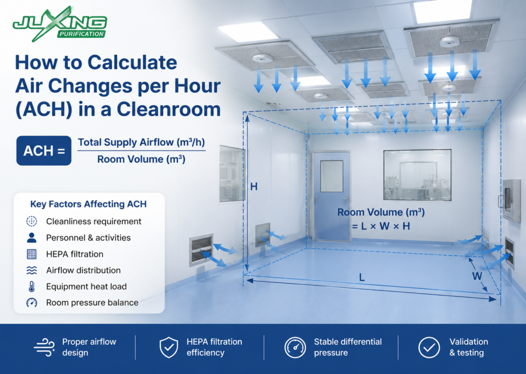
Air Changes per Hour, commonly abbreviated as ACH, is widely used in cleanroom and controlled-environment design. It expresses the total supply airflow delivered to a room in one hour as a multiple of the room’s internal volume.
ACH can help engineers estimate the airflow required for contaminant dilution, particle removal, temperature control, humidity control and cleanliness recovery. However, it is frequently misunderstood.
A higher ACH does not automatically create a cleaner room, and an ISO cleanroom class cannot be selected from an ACH table alone. Cleanroom performance depends on the interaction between:
- Airborne contamination generation
- Supply-air filtration
- Airflow distribution
- Return- and exhaust-air locations
- Personnel activity
- Process equipment
- Room pressure
- Temperature and humidity loads
- Operating procedures
- Testing and qualification
ISO 14644-1 classifies cleanrooms according to airborne particle concentration. It does not assign one mandatory air-change rate to each ISO class.
This guide explains how to calculate ACH correctly, how to convert a target ACH into required supply airflow, and why the calculated figure must be evaluated together with the complete cleanroom ventilation system.
What Does ACH Mean?
ACH indicates how many room-volume equivalents of supply air enter a room during one hour.
For example, consider a room with an internal volume of 100 m³ receiving 3,000 m³/h of supply air:
ACH = 3,000 m³/h ÷ 100 m³
ACH = 30
The room therefore receives a quantity of supply air equivalent to 30 times its internal volume every hour.
This does not mean that every air molecule is completely removed and replaced exactly 30 times.
In a real room, supplied air mixes with existing air. Some air may move efficiently from the supply terminals toward the return grilles, while some may circulate around equipment or remain in poorly ventilated areas.
The actual contaminant-removal performance therefore depends on more than airflow volume. It also depends on:
- Supply-terminal arrangement
- Return-air grille position
- Room geometry
- Equipment layout
- Airflow obstructions
- Air mixing
- Thermal currents
- Contamination-source location
ACH should consequently be treated as an airflow-design parameter, not as a direct measurement of cleanliness.
The Formula for Calculating ACH
When airflow is expressed in cubic metres per hour, the standard calculation is:
ACH = Total Supply Airflow (m³/h) ÷ Room Volume (m³)
Room volume is calculated as:
Room Volume = Internal Length × Internal Width × Clear Height
The dimensions should represent the actual internal air volume of the cleanroom.
Example
Assume that a cleanroom has the following dimensions:
- Internal length: 8 m
- Internal width: 6 m
- Clear height: 3 m
The room volume is:
8 × 6 × 3 = 144 m³
If the measured or designed total supply airflow is 7,200 m³/h:
ACH = 7,200 ÷ 144
ACH = 50
The calculated air-change rate is therefore 50 ACH.
This means that the room receives a supply-air quantity equivalent to 50 room volumes per hour.
How to Calculate the Required Supply Airflow
When the target ACH has already been selected, the formula can be rearranged:
Required Supply Airflow = Room Volume × Target ACH
Using the same room volume of 144 m³, suppose the preliminary design target is 40 ACH:
Required Supply Airflow = 144 × 40
Required Supply Airflow = 5,760 m³/h
The preliminary total supply-air requirement is therefore 5,760 m³/h.
This airflow could be delivered through:
- Terminal HEPA filter boxes
- Ceiling-mounted HEPA supply units
- Fan filter units
- Conventional supply diffusers
- A central air-handling system
- A combined AHU and FFU arrangement
The final terminal quantity cannot be determined from airflow alone. Terminal size, rated airflow, pressure drop, ceiling coverage, room layout and airflow distribution must also be considered.
Which Airflow Should Be Used in the ACH Calculation?
Cleanroom airflow calculations often become confusing because several different airflow quantities may appear on the drawings.
These quantities should not be treated as interchangeable.
Total Supply Airflow
Total supply airflow is the total quantity of air delivered into the room through all active supply terminals.
For most cleanroom ACH calculations, this is the principal value used.
Outdoor Airflow
Outdoor airflow, also called fresh air or make-up air, is the portion introduced from outside the building.
It may be required for:
- Occupancy ventilation
- Replacing exhausted air
- Maintaining room pressurisation
- Controlling odours or vapours
- Meeting applicable building or healthcare requirements
Outdoor airflow is normally only part of the total supply airflow.
Recirculated Airflow
Recirculated air is returned from the cleanroom, reconditioned and filtered before being supplied again.
Many cleanrooms use a high recirculation ratio because the total airflow needed for particle control is much greater than the required outdoor-air quantity.
Exhaust Airflow
Exhaust air is removed from the building rather than returned to the system.
Dedicated exhaust may be required for rooms handling:
- Hazardous chemicals
- Potent compounds
- Infectious materials
- Powders
- Solvents
- Strong odours
- Process heat or moisture
Equivalent Air Changes
Portable or recirculating air-cleaning devices are sometimes described as providing equivalent air changes.
Equivalent ACH can be useful for evaluating air-cleaning capacity, but it should not automatically be added to mechanical supply ACH without understanding the calculation method, filter efficiency and airflow path. ASHRAE guidance also distinguishes equivalent room air exchanges from required outdoor-air changes.
Does ISO 14644 Specify ACH for Each Cleanroom Class?
No.
ISO 14644-1 establishes cleanroom classification based on the concentration of airborne particles within specified particle-size ranges.
It does not state that:
- ISO Class 8 must always use a particular ACH;
- ISO Class 7 must always use another fixed ACH;
- ISO Class 5 must always use several hundred ACH.
Figures such as “ISO Class 7 equals 30–60 ACH” are commonly used as preliminary industry references, but they are not ISO 14644 requirements.
Two ISO Class 7 rooms may operate at different air-change rates because they may have different:
- Occupancy levels
- Garment systems
- Process particle generation
- Equipment heat loads
- Room dimensions
- Airflow patterns
- Recovery requirements
- Operating schedules
- At-rest and operational conditions
One room may maintain the required particle concentration with a lower airflow because it has limited occupancy and well-positioned supply and return terminals.
Another room with the same ISO classification may require substantially more airflow because it contains multiple operators, particle-generating equipment or a demanding recovery-time requirement.
The correct approach is therefore:
- Establish the required cleanliness condition.
- Assess contamination and environmental loads.
- Select a preliminary airflow strategy.
- Design the supply, return and exhaust arrangement.
- Test the completed room.
- Adjust and balance the system if required.
Why ACH Cannot Be Compared Directly with an Operating Theatre Classification
A conventional operating theatre and an ISO-classified industrial cleanroom are not necessarily evaluated under the same framework.
Cleanroom classification under ISO 14644-1 concerns airborne particle concentration.
Healthcare ventilation standards may instead specify combinations of:
- Total air changes
- Outdoor air changes
- Positive or negative pressure
- Supply-air filtration
- Temperature
- Relative humidity
- Air-distribution pattern
- Exhaust or return arrangement
- Infection-control requirements
For example, published ASHRAE material describes a conventional operating room with a total supply rate of 20 ACH, including 4 ACH of outdoor air, together with positive pressure and a defined downward supply-air pattern.
This does not mean that an operating room is automatically cleaner or less clean than an ISO Class 7 cleanroom.
It means that the two rooms may be designed and assessed according to different functional and regulatory criteria.
An ultraclean or unidirectional-flow operating theatre also cannot be adequately described by one ACH figure. The design must consider:
- Size of the protected surgical zone
- Ceiling-array coverage
- Downward airflow
- Air velocity
- Surgical lights and pendants
- Staff positions
- Equipment obstructions
- Return-air arrangement
- Contamination entering the protected zone
NHS England’s HTM 03-01 likewise treats specialised healthcare ventilation as a coordinated design, operational and maintenance matter rather than reducing performance to one generic ACH table.
What Determines the Required Cleanroom ACH?
Because no universal ISO-to-ACH conversion exists, the required airflow must be developed from project-specific conditions.
1. Cleanliness Requirement
A more stringent particle-concentration limit generally requires stronger contaminant control.
However, cleanliness class alone is not sufficient to determine the airflow rate. The room must also be assessed under the specified occupancy and operating condition.
An at-rest cleanroom may contain installed equipment but no operating personnel. An operational cleanroom includes the specified process and personnel activities.
The airflow required to maintain classification under operational conditions may be higher than the airflow needed during an at-rest test.
2. Personnel and Gowning
Personnel are often a major source of contamination.
Particle release can vary according to:
- Number of operators
- Type and quality of cleanroom garments
- Movement speed
- Work activity
- Gowning discipline
- Frequency of entry and exit
- Door-opening frequency
Increasing ACH may improve dilution, but good gowning and behaviour control remain essential. Ventilation cannot fully compensate for poor cleanroom discipline.
3. Process Contamination
The type and location of process-generated contamination strongly affect airflow design.
Processes may generate:
- Non-viable particles
- Microorganisms
- Powder
- Vapour
- Fume
- Aerosol
- Moisture
- Heat
A general room ACH calculation may be insufficient where contamination is released at a concentrated source.
Local exhaust, containment devices, isolators or unidirectional airflow may be more effective than simply increasing the whole-room airflow.
4. Equipment Heat Load
Cleanroom equipment, lighting, personnel and processes release heat.
In some projects, the airflow required to remove heat is greater than the airflow initially estimated for particle control.
The designer should therefore calculate and compare:
- Airflow required for cleanliness
- Airflow required for cooling
- Airflow required for humidity control
- Airflow required for exhaust replacement
- Airflow required for room pressurisation
The final supply-air quantity should satisfy all applicable requirements rather than only the ACH target.
5. Airflow Distribution
A high ACH with poor distribution may perform worse than a lower ACH with a well-designed airflow pattern.
Poor design can create:
- Dead zones
- Airflow short circuits
- Local turbulence
- Particle accumulation
- Uneven temperature
- Unprotected critical work areas
A short circuit occurs when supply air moves directly toward a nearby return grille without effectively sweeping the occupied or process zone.
Airflow visualisation can help identify these problems during commissioning. ISO 14644-3 covers test methods for assessing cleanroom and clean-zone performance.
6. Return-Air and Exhaust-Air Locations
Return grilles establish the path through which supplied air leaves the room.
Their location should be coordinated with:
- Supply-terminal positions
- Process equipment
- Workstations
- Doors
- Partitions
- Contamination sources
- Room pressure requirements
Low-level returns are frequently used in cleanroom and operating-room designs, but they should not be applied as a universal rule.
The correct arrangement depends on the intended airflow pattern and room function.
7. Differential Pressure
ACH and differential pressure are related, but they are not the same parameter.
ACH describes total supply airflow relative to room volume.
Differential pressure results from the airflow imbalance between connected spaces and the resistance of leakage paths.
A positive-pressure room generally receives more supply air than the combined return and exhaust airflow. The surplus air moves toward adjacent lower-pressure areas through designed transfer paths and unavoidable leakage openings.
A negative-pressure room generally removes more air than it receives, drawing air inward from surrounding spaces.
Doors, pass boxes, wall joints, ceiling penetrations and service openings all influence the airflow offset required to maintain the pressure relationship.
ACH and HEPA Filtration
ACH and filtration efficiency describe different parts of cleanroom performance.
ACH describes airflow quantity.
HEPA or ULPA efficiency describes how effectively a filter removes specified particles from the air passing through it.
A high-efficiency filter will not protect the room adequately if:
- Airflow is insufficient
- The filter is bypassed
- The seal leaks
- The terminal is badly positioned
- Return-air design creates stagnant zones
- The filter has not passed an integrity test
Likewise, increasing airflow cannot compensate for a damaged or incorrectly installed filter.
A reliable cleanroom system requires:
- Suitable final-filter efficiency
- Correct filter installation
- Adequate supply airflow
- Appropriate terminal coverage
- Balanced return and exhaust airflow
- Filter integrity testing
- Periodic maintenance
Calculating ACH from Multiple HEPA Terminals or FFUs
When several supply units serve the same room, add their actual airflow values before calculating ACH.
Suppose a cleanroom has eight terminal HEPA filter boxes, each delivering 1,000 m³/h:
Total Supply Airflow = 8 × 1,000
Total Supply Airflow = 8,000 m³/h
If the room volume is 160 m³:
ACH = 8,000 ÷ 160
ACH = 50
The calculated room air-change rate is 50 ACH.
However, the calculation is only as accurate as the airflow data used.
A nominal catalogue airflow is not always the same as the actual commissioned airflow. Delivered airflow may be affected by:
- Fan performance
- Duct pressure loss
- Damper setting
- HEPA filter resistance
- Filter loading
- System leakage
- Control settings
- Terminal balancing
Commissioned or measured airflow should therefore be used when verifying the final ACH.
Common ACH Calculation and Design Mistakes
Treating ACH as a Cleanroom Class
A room does not become ISO Class 7 merely because it is designed at a commonly referenced ISO Class 7 airflow rate.
Classification must be demonstrated through airborne particle testing.
Using Outdoor Air Instead of Total Supply Air
If a room receives 6,000 m³/h of total supply air but only 600 m³/h of outdoor air, using 600 m³/h in the cleanroom ACH calculation would significantly understate the recirculating ventilation rate.
The drawing and specification should clearly distinguish the two values.
Using the Wrong Room Height
The calculation should normally use the actual cleanroom clear height, not the floor-to-floor structural height.
Where large ceiling voids or open connected volumes form part of the controlled space, the project engineer should define the applicable room volume.
Using Nominal Equipment Capacity
Do not assume that eight units labelled “1,000 m³/h” will always deliver exactly 8,000 m³/h after installation.
Actual airflow must be measured and balanced.
Ignoring Airflow Obstructions
Large production equipment, storage racks, partitions, cabinets, surgical lights and ceiling-mounted services may disturb the intended airflow path.
Increasing ACH Without Checking the System
Increasing airflow may require modifications to:
- Fan capacity
- Duct size
- Damper arrangement
- Cooling and heating coils
- Dehumidification capacity
- Return-air grilles
- Exhaust systems
- HEPA filter area
It may also increase noise, draughts, energy use and filter pressure loss.
How Should the Selected ACH Be Verified?
The selected ACH should be treated as an initial design input that must be confirmed through testing and commissioning.
Depending on the cleanroom and project specification, verification may include:
- Supply-air volume measurement
- Return- and exhaust-air measurement
- Air velocity testing
- HEPA filter integrity testing
- Differential-pressure testing
- Airflow visualisation
- Airborne particle counting
- Recovery-time testing
- Temperature mapping
- Relative-humidity mapping
ISO 14644-3 describes test methods for measuring cleanroom and clean-zone performance, reinforcing the principle that the completed system must be evaluated by measurement rather than accepted from a theoretical ACH figure alone.
Expert Tip
When reviewing a cleanroom quotation, do not accept a statement such as “the room is designed at 50 ACH” without supporting information.
Ask the supplier or contractor to provide:
- Internal room dimensions
- Room volume
- Total supply airflow
- Outdoor airflow
- Return airflow
- Exhaust airflow
- Number of HEPA terminals or FFUs
- Design airflow per terminal
- Pressure-offset airflow
- Intended room condition
- Airflow-measurement method
- Testing and commissioning scope
This makes it possible to determine whether the quoted ACH is based on a coordinated ventilation design or has simply been copied from a general reference table.
Frequently Asked Questions
What is the formula for cleanroom ACH?
The basic metric formula is:
ACH = Total Supply Airflow (m³/h) ÷ Room Volume (m³)
Room volume is normally calculated using the internal room length, width and clear height.
Does ISO 14644 specify the ACH for ISO Class 7?
No. ISO 14644-1 classifies air cleanliness according to airborne particle concentration. It does not prescribe a single air-change rate for every ISO Class 7 cleanroom.
Is 30–60 ACH always correct for ISO Class 7?
No. That range is commonly cited as preliminary design guidance, but it is not a universal requirement.
The actual airflow depends on occupancy, contamination generation, room layout, airflow distribution, heat load, recovery requirements and validation results.
Does 20 ACH mean that an operating theatre is less clean than an ISO Class 7 room?
No.
A conventional operating theatre designed at 20 total ACH and an ISO Class 7 cleanroom are not necessarily being evaluated according to the same criteria. ACH alone cannot establish a direct cleanliness comparison.
Is cleanroom ACH based on outdoor air only?
Normally no.
Cleanroom ACH is generally calculated from total supply airflow, which may include both recirculated and outdoor air.
Outdoor-air changes should be identified separately.
Can higher ACH improve cleanroom performance?
It can improve particle dilution and shorten recovery time when the filtration and airflow distribution are effective.
However, higher ACH cannot correct filter leakage, poor terminal placement, serious airflow obstructions or uncontrolled contamination sources.
How many HEPA terminals does a cleanroom require?
A preliminary quantity may be estimated by dividing the required total supply airflow by the design airflow per terminal.
The final quantity must also consider:
- Ceiling coverage
- Terminal dimensions
- Airflow distribution
- Room shape
- Equipment layout
- Filter resistance
- System pressure
- Maintenance access
Should ACH be calculated from design airflow or measured airflow?
Design airflow may be used during the engineering stage.
After installation, final ACH should preferably be confirmed using measured and balanced supply airflow.
Conclusion
Air Changes per Hour is a useful cleanroom ventilation parameter, but it must be interpreted correctly.
ACH indicates how much supply air enters a room relative to its internal volume. It does not mean that all room air is completely replaced that number of times, and it does not independently determine the ISO cleanliness class.
ISO 14644-1 classifies cleanrooms according to airborne particle concentration rather than a fixed ACH schedule.
A technically sound cleanroom airflow design must consider:
- Required particle concentration
- At-rest and operational conditions
- Personnel and gowning
- Process contamination
- Heat and humidity loads
- Filter efficiency
- Supply-air distribution
- Return and exhaust arrangement
- Differential pressure
- Recovery requirements
- Testing and commissioning
The objective should not be to specify the highest possible ACH.
The objective is to provide sufficient, properly filtered and properly distributed airflow so that the completed cleanroom consistently achieves its required environmental performance without unnecessary energy consumption, noise or operating cost.