
Introduction
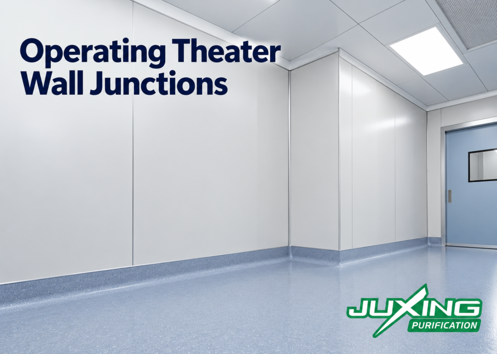
Operating theater wall junctions are small construction details with a large effect on hygiene, cleaning, airtightness, maintenance and visual quality. Even when the wall panels, ceiling panels and flooring are individually suitable, poor coordination at their intersections can leave open gaps, dirt traps, cracked sealant or inaccessible fixing points.
The two most important interfaces are:
- The wall-to-ceiling junction, where modular wall panels meet the ceiling system and overhead services
- The wall-to-floor junction, where the hygienic wall finish meets the floor covering, coving or skirting system
These junctions must be designed as parts of the complete operating theater envelope. They should not be treated as decorative trim added after the walls, ceiling and flooring have already been selected.
ISO 14644-4:2022 provides a lifecycle framework for cleanroom design, construction and start-up, but it does not prescribe one universal wall-to-ceiling or wall-to-floor profile. The final detail must therefore follow the project specification, local healthcare guidance, fire strategy, cleaning requirements and selected construction system. iso.org
Quick Answer
Operating theater wall junctions should provide a smooth, cleanable and maintainable transition between the wall system, ceiling and floor. The correct detail depends on the wall construction, ceiling type, finished floor level, required access, expected movement and project-specific airtightness or fire requirements.
A well-designed junction normally includes:
- Continuous structural support behind the visible finish
- Controlled panel and profile tolerances
- A cleanable transition without exposed rough edges
- Compatible gaskets, sealants or cover profiles
- Allowance for installation sequence and building movement
- Coordination with fire stopping and service penetrations
- Access provisions where adjacent panels or ceilings are removable
A curved floor cove and a sealed ceiling perimeter are common solutions, but neither is automatically required by every international standard or suitable for every project.
Key Takeaways
- Operating theater wall junctions must be coordinated before panel fabrication.
- Wall panels should not be used to support heavy ceiling-mounted medical equipment.
- The wall-to-ceiling detail must account for ceiling movement, access and service coordination.
- The wall-to-floor detail must be based on the final finished floor level, not only the structural slab level.
- Flooring coves, metal skirtings and sealant joints perform different functions.
- A smooth-looking joint is not necessarily airtight, fire-rated or waterproof.
- Fire performance must be assessed as part of the complete wall, ceiling and penetration assembly.
- Removable wall panels require junction details that allow future access without damaging the floor or ceiling.
- Junction profiles should be selected according to the actual wall and ceiling system rather than assumed from a standard catalogue detail.
Why Are Operating Theater Wall Junctions So Important?
Wall junctions connect different materials installed by different trades. The wall-panel contractor, ceiling installer, flooring contractor, HVAC contractor and medical-equipment installer may all affect the same perimeter detail.
Problems frequently occur when each trade works from a separate drawing. Examples include:
- Ceiling panels finishing short of the wall
- Wall panels extending too high for ceiling installation
- Floor coving conflicting with removable wall panels
- Sealant joints wider than expected because of dimensional errors
- Exposed panel edges around ceiling perimeters
- Gaps behind skirting profiles
- Fire stopping omitted above the visible ceiling
- Access panels blocked by perimeter trims
- Wall joints failing to align with ceiling grids or built-in equipment
The architectural finish may conceal some of these defects temporarily, but movement, cleaning and maintenance often expose them later.
For an overview of the complete enclosure, see the modular operating theater wall and ceiling systems guide.
How Should a Wall-to-Ceiling Junction Be Designed?
A wall-to-ceiling junction usually includes more than the visible meeting line. It may involve:
- The main structural frame or secondary steelwork
- Wall-panel supporting channels or hooks
- Ceiling suspension members
- Perimeter ceiling trim
- Wall and ceiling finish panels
- Gaskets or sealant
- Fire or smoke barriers where required
- Above-ceiling services and access zones
The visible finish should be smooth and cleanable, but the concealed support arrangement is equally important.
Common wall-to-ceiling configurations
| Configuration | Typical advantages | Main coordination concerns |
|---|---|---|
| Ceiling panel terminates against wall face | Simple visible perimeter and clear separation between systems | Sealant width, movement and ceiling access |
| Wall panel extends above finished ceiling | Helps conceal perimeter tolerances and supports a continuous wall line | Ceiling installation sequence and hidden sealing |
| Ceiling perimeter trim overlaps wall panel | Can create a neat, factory-defined edge | Profile cleanability and compatibility with removable panels |
| Gasketed wall-to-ceiling profile | Allows controlled dry-joint construction | Gasket compression, corner continuity and replacement |
| Sealed metal angle or flashing | Adaptable to site conditions | Exposed fasteners, sealant quality and appearance |
| Radius or coved ceiling transition | Smooth visual and cleaning transition | Fabrication accuracy and access above the ceiling |
No single configuration is automatically superior. The correct choice depends on whether the ceiling is fixed, demountable, clip-in, gasketed or locally accessible.
The ceiling design should also be coordinated with the differences explained in the operating theater ceiling systems comparison.
Should the Wall Panels Extend Above the Finished Ceiling?
Extending the wall panels above the ceiling line is a common project detail, but it is not a universal international requirement.
Possible reasons include:
- Closing the room perimeter above the visible ceiling
- Providing tolerance for ceiling-level variations
- Supporting a continuous barrier where required by the design
- Reducing the risk of open gaps above perimeter trims
- Simplifying coordination between the wall and ceiling finishes
However, the required extension height must be defined by the project designer. It may depend on:
- Above-ceiling pressure relationships
- Fire and smoke compartmentation
- Structural framing
- Ceiling support locations
- Service routes
- Inspection access
- Acoustic requirements
- Local healthcare and building regulations
An extension of 200, 300 or another number of millimetres should be treated as a project-specific dimension, not as an ISO requirement.
Where the wall stops above the ceiling, the concealed section may not require the same decorative finish as the exposed room surface. It still needs suitable corrosion protection, secure fixing and coordination with any barriers or sealants.
Can the Modular Wall Support the Ceiling or Heavy Equipment?
The answer depends on the engineered system, but decorative wall panels should not be assumed to be structural supports.
The following loads normally require independent structural assessment and support:
- Surgical lights
- Medical pendants
- Equipment booms
- Laminar airflow ceilings
- Heavy terminal filter housings
- Large ceiling access units
- Ceiling-mounted monitors
- Service bridges
These loads are commonly transferred to the building structure or a dedicated steel support frame. The modular wall and ceiling finishes then close around the independently supported equipment.
Light perimeter trims may be fixed to wall framing where the system is designed for them. This does not mean the wall panels can support major suspended equipment.
The structural responsibility, design loads, deflection limits and fixing method should be clearly identified in the project documents.
How Should Ceiling Movement Be Accommodated?
Wall and ceiling systems may move differently because of:
- Building deflection
- Thermal expansion
- Pressure changes
- Vibration
- Installation tolerances
- Loading of the ceiling support grid
- Seismic movement in relevant locations
A completely rigid finish at the perimeter may crack if movement has not been considered. Conversely, an excessively flexible joint may open, collect contamination or lose its intended sealing function.
Possible movement-control methods include:
- Correctly sized elastic sealant joints
- Compressible gaskets
- Sliding or overlapping perimeter profiles
- Separate wall and ceiling support structures
- Movement joints aligned with structural joints
The sealant manufacturer’s stated movement capability must match the designed joint width and expected movement. Applying a thin surface smear over an uncontrolled gap is not an adequate movement joint.
How Should a Wall-to-Floor Junction Be Designed?
The wall-to-floor junction must coordinate four levels:
- Structural slab level
- Screed or raised-floor level
- Finished floor level
- Bottom edge of the wall panel or skirting profile
The wall-panel manufacturer needs the final finished floor level before production. If the panel height is based on the slab and the floor build-up later changes, the bottom joint may become too small, too large or uneven.
A typical wall-to-floor interface may include:
- Bottom wall channel or adjustable floor track
- Wall-panel lower edge
- Hygienic skirting or cove former
- Resilient sheet flooring or resin flooring
- Sealant or gasket
- Floor adhesive and substrate preparation
- Local waterproofing where specified
Flooring guidance for healthcare environments considers cleaning, spillages, rolling loads and the intended room function. It should be coordinated with the wall system instead of selected independently. NHS HBN 00-10 Part A, for example, discusses flooring performance in healthcare spaces, including operating-theater loading and cleaning conditions, but the applicable requirements still depend on the project location. Flooring
Is a Coved Floor Junction Always Required?
A coved transition is widely used in operating theaters because it removes a sharp internal corner and can simplify cleaning. However, the exact cove material, height and radius are normally determined by the flooring specification or local healthcare requirements.
Common options include:
Resilient sheet flooring turned up the wall
The flooring is formed over a cove former and extended vertically behind or against the wall finish.
Important considerations include:
- Minimum bending radius of the flooring
- Heat-welded seams
- Cove height
- Adhesive compatibility
- Termination beneath the wall panel or trim
- Replacement procedure
Prefabricated hygienic skirting
A metal, PVC or other compatible profile forms the transition.
Important considerations include:
- Cleanability
- Impact resistance
- Joint continuity
- Fixing method
- Compatibility with cleaning chemicals
- Internal and external corner pieces
Resin floor with an integral cove
The floor finish is continued into a formed wall upstand.
Important considerations include:
- Substrate preparation
- Crack control
- Cove reinforcement
- Thickness consistency
- Termination against the wall panel
- Repair procedure
A visible radius alone does not prove that the junction is waterproof, airtight or hygienic. Performance depends on the complete construction and workmanship.
How Should Removable Wall Panels Meet the Floor?
A removable panel should be capable of being released without destroying the finished floor or permanent coving.
Potential conflicts include:
- Flooring turned up directly over the removable panel
- Skirting fixed across panel joints
- Sealant bonding the panel permanently to the floor
- Insufficient clearance for lifting the panel off its hooks
- Bottom trims blocking panel movement
- Cabinets or equipment preventing access to the panel edge
Where panels use rear hooks, the removal direction must be considered. Some panels need to move upward before being pulled forward. The floor junction must leave enough movement space without creating an unacceptable exposed gap.
Possible design approaches include:
- A removable lower trim
- A gasketed bottom profile
- A separate fixed plinth below the removable panel
- A controlled sealant joint that can be cut and renewed
- A cove attached to a permanent backing rather than the removable facing panel
The exact arrangement should be demonstrated with a full-size detail or mock-up before mass production.
For further information about panel movement and fixing, see removable operating theater wall panels and rear-hook systems.
How Do Wall Junctions Affect Airtightness?
Room pressure depends on the entire enclosure and ventilation system. A positive-pressure reading does not prove that every junction is completely airtight.
Potential leakage paths at wall junctions include:
- Discontinuous ceiling-perimeter seals
- Gaps behind skirting profiles
- Open corners between intersecting trims
- Unsealed fixings
- Service penetrations near the ceiling
- Poor gasket compression
- Cracked sealant
- Open spaces behind built-in cabinets
- Incomplete barriers above the visible ceiling
Airtightness requirements should be defined by the project team. If room-envelope leakage testing is required, the acceptance criteria, test condition and responsibility for temporary sealing should be agreed before construction.
Smoke pencils and airflow visualization may help identify local leakage, but they do not replace a specified quantitative leakage test where one is required.
How Should Fire Performance Be Addressed at the Junctions?
Metal wall or ceiling surfaces do not automatically make the complete construction fire-rated.
Fire performance may depend on:
- Wall and ceiling facings
- Backing boards
- Core materials
- Adhesives
- Support framing
- Joint profiles
- Gaskets and sealants
- Cavity barriers
- Fire stopping
- Service penetrations
- Junction with the structural building elements
If a wall or ceiling forms part of a fire-resisting compartment, the perimeter detail must be consistent with the tested or assessed assembly. Substituting a profile, backing board, sealant or fixing method may affect the claimed performance.
A hygienic surface seal should not be assumed to provide fire stopping. Likewise, concealed fire stopping may not provide the cleanable exposed finish needed inside the operating theater. Both functions may require separate materials.
How Should Services Near the Junctions Be Coordinated?
The ceiling perimeter often contains or passes close to:
- Medical gas pipes
- Electrical conduits
- Data cables
- Sprinkler pipes
- Fire-alarm devices
- Pressure-sensing tubes
- Air ducts
- Lighting cables
- Ceiling access points
The wall base may also contain electrical conduits, floor boxes or drainage components.
The design should maintain clear zones for:
- Panel hooks and fasteners
- Ceiling hangers
- Sealant or gasket installation
- Fire stopping
- Inspection
- Future maintenance
- Panel removal
Service penetrations should not be drilled through critical junction profiles without an approved detail. Unplanned site openings can damage coatings, interrupt seals and weaken supporting members.
What Should Be Shown on the Coordination Drawings?
At minimum, the wall-junction package should include:
| Drawing or document | Information required |
|---|---|
| Room elevations | Wall-panel divisions, ceiling line, floor line and embedded items |
| Reflected ceiling plan | Ceiling grid, perimeter panels, access panels, diffusers and equipment |
| Wall-to-ceiling section | Panel extension, profiles, supports, seals and above-ceiling barrier |
| Wall-to-floor section | Finished floor level, floor build-up, cove, skirting and bottom track |
| Corner details | Internal and external profile continuity |
| Service details | Penetration locations and sealing method |
| Fire-stopping details | Tested or assessed perimeter and penetration arrangement |
| Removal diagram | Direction and clearance needed to remove panels |
| Interface matrix | Responsibility of each trade |
| Mock-up checklist | Appearance, cleanability, access and tolerance checks |
Dimensions should be referenced to agreed project datums. “Site measure” should not replace the coordinated design information needed for factory production.
What Installation Sequence Reduces Junction Problems?
A practical sequence may include:
- Verify the structural slab, walls and ceiling support locations.
- Establish finished floor and ceiling datums.
- Install independent structural supports for heavy equipment.
- Set out the wall tracks and primary framing.
- Coordinate concealed services.
- Install required backing, barriers and fire stopping.
- Install wall panels according to the approved sequence.
- Install the ceiling perimeter and ceiling panels.
- Complete the floor substrate and floor finish.
- Install coving, skirting or bottom trims.
- Apply final gaskets and sealants.
- Inspect corners, penetrations and removable-panel clearances.
- Perform specified cleaning and envelope tests.
- Record approved details in the as-built documents.
The actual sequence may differ according to the selected system. It should be agreed before site work begins, especially when several contractors share the interfaces.
The broader installation process is explained in the modular operating theater installation guide.
How Should the Finished Junctions Be Inspected?
Inspection should cover more than appearance.
Visual checks
- Consistent joint width
- Complete gasket engagement
- Smooth sealant surfaces
- No exposed raw panel edges
- No sharp projections
- Clean internal and external corners
- No visible corrosion or coating damage
- Correct alignment with doors, cabinets and panel joints
Functional checks
- Removable panels can be accessed as intended
- Ceiling access panels can open fully
- Skirting does not block panel removal
- Floor coving remains securely bonded
- Junctions tolerate normal cleaning
- Specified leakage tests meet the project criteria
- Fire stopping and penetration seals are documented
- Defects are recorded before final handover
A mock-up can be particularly valuable because it allows the wall, ceiling and flooring contractors to agree on the sequence and finished appearance before multiple rooms are installed.
Buyer’s Checklist
Before approving operating theater wall junctions, confirm:
- The final finished floor and ceiling levels are defined.
- Wall-to-ceiling and wall-to-floor sections are included in the approved drawings.
- Panel thicknesses, profiles and support framing are specified.
- Wall-panel extension above the ceiling is defined where required.
- Heavy ceiling equipment has independent structural support.
- The ceiling perimeter permits required access and removal.
- The floor cove or skirting material is identified.
- Removable panels are not permanently trapped by the flooring detail.
- Sealant and gasket materials are compatible with cleaning chemicals.
- Expected movement and joint widths have been considered.
- Fire stopping is distinguished from hygienic surface sealing.
- Service penetrations have coordinated locations and sealing details.
- Internal and external corner details are included.
- Trade responsibilities are recorded in an interface matrix.
- A mock-up or first-room inspection is planned.
- As-built details and maintenance instructions will be provided.
Common Misconceptions
“A curved junction is automatically hygienic.”
A curve may improve cleanability, but poor bonding, open ends or cracked sealant can still create contamination traps.
“Silicone can correct any construction gap.”
Sealant has limits for joint width, depth, adhesion and movement. Large or irregular gaps normally require corrected construction or an engineered profile.
“Positive room pressure proves that all perimeter joints are airtight.”
Room pressure is a system-level result. Local leakage can still exist at wall, ceiling, floor, door or service interfaces.
“The metal wall panel can support the laminar airflow ceiling.”
Heavy ceiling equipment normally requires independent support unless the complete system has been specifically engineered for the load.
“ISO 14644 specifies the exact cove radius and profile dimensions.”
ISO 14644 does not establish one universal operating-theater junction geometry. Dimensions must come from the project specification and the selected system.
“A metal profile automatically provides a fire-rated junction.”
Fire resistance must be supported by the complete tested or assessed assembly, including concealed materials and penetration treatments.
Expert Tip
Approve the wall-to-ceiling and wall-to-floor details together, not as separate packages.
A change to the finished floor level can alter the wall-panel height. A change to the ceiling grid can affect the top panel, perimeter seal and access arrangement. Reviewing both junctions on one coordinated room elevation makes dimensional conflicts easier to identify before fabrication.
Where removable panels are required, ask the supplier to demonstrate the removal path in the mock-up. A panel that is technically removable but trapped by coving, ceiling trims or built-in equipment will not provide practical maintenance access.
Frequently Asked Questions
What is the best wall-to-ceiling junction for an operating theater?
There is no universal best detail. The correct solution depends on the wall and ceiling systems, access requirements, movement, fire strategy and project-specific sealing criteria.
Should the wall panel continue above the operating theater ceiling?
It may be required to support the enclosure design or conceal perimeter tolerances, but the extension height is project-specific. It should be shown on the coordinated sections.
Does the ceiling need to be sealed to the wall?
Many operating-theater designs use a sealed or gasketed perimeter, but the required sealing performance must be defined by the project. The detail must also permit necessary access and movement.
What is the recommended floor-cove height?
There is no single international height applicable to every operating theater. The flooring specification, cleaning protocol and local healthcare requirements should define the cove height.
Can vinyl flooring be turned up directly behind a metal wall panel?
Yes, in some systems. The detail must coordinate adhesive, termination height, wall fixing and future panel removal. The wall panel should not compress or damage the flooring.
Can a removable wall panel be sealed at the floor?
Yes. A renewable sealant joint, gasket or removable trim may be used. The sealing method should allow the panel to be removed without damaging the permanent floor finish.
Should wall-to-floor joints be completely waterproof?
That depends on the room and cleaning method. A cleanable joint does not automatically provide waterproofing. If water resistance is required, the complete floor and wall interface must be designed and tested accordingly.
Who is responsible for the junction details?
Responsibility may be shared among the architect, operating-theater designer, wall-system supplier, ceiling supplier, flooring contractor and fire consultant. The contract documents should clearly assign design, supply and installation responsibilities.
Does JUXING supply the complete operating theater floor system?
JUXING can manufacture modular operating theater walls, ceilings, doors, built-in cabinets and related cleanroom components according to approved drawings. Complete floor finishes are not normally part of JUXING’s standard supply scope, but their dimensions and interface requirements must be coordinated with the modular wall system.
Should the junction details be tested in a mock-up?
A mock-up is strongly recommended for complex or repeated projects. It allows the project team to evaluate tolerances, cleaning access, visual quality, seal continuity and panel removability before full production.
Conclusion
Operating theater wall junctions should be designed as functional interfaces rather than decorative finishing details. The wall-to-ceiling connection must coordinate ceiling support, access, movement, sealing and overhead services. The wall-to-floor connection must coordinate the finished floor level, coving, skirting, bottom tracks and removable-panel requirements.
Successful junction design depends on early coordination between the wall-panel manufacturer, ceiling supplier, flooring contractor, structural engineer, fire consultant and MEP team. Exact profiles and dimensions should be based on approved project drawings and the selected construction system—not assumed to be universal requirements.
When these details are resolved before fabrication, the completed operating theater is easier to install, clean, inspect, maintain and modify throughout its service life.