
Introduction
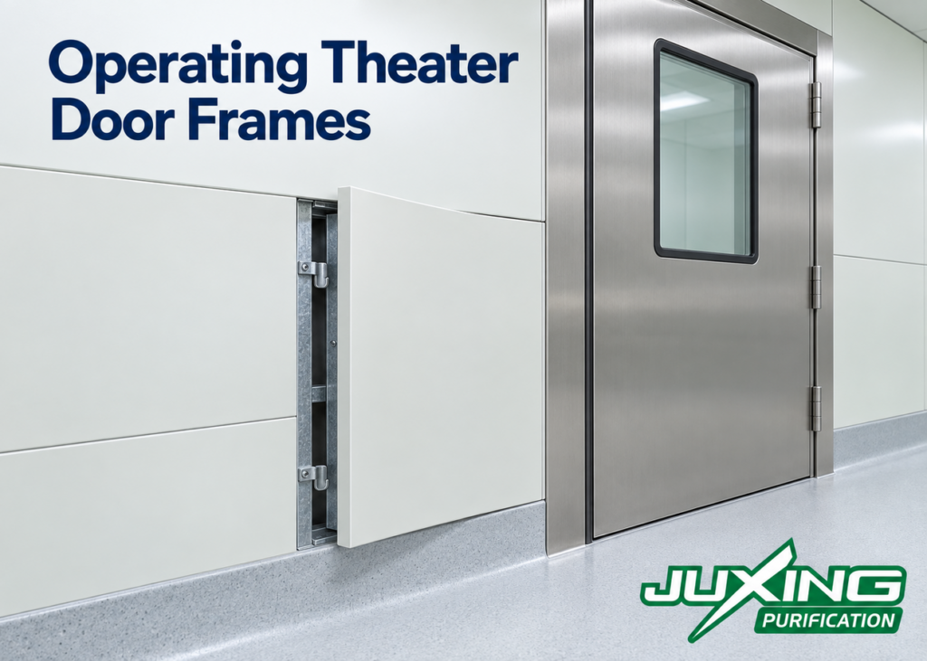
Operating theater door frames must be coordinated with removable wall panels before either component enters production. If the frame, panel edges, concealed fixings, gaskets, structural supports, and door services are designed separately, the finished interface may look acceptable but prevent panel removal, interrupt the room seal, or transfer door loads into a non-structural wall facing.
This interface becomes more demanding when the project uses heavy swing doors, automatic sliding doors, lead-lined doors, three-section walls, or individually removable panels. Each system has a different support and access requirement.
A successful detail must distinguish between four functions:
- Structural support for the door assembly
- Hygienic closure at the exposed perimeter
- Environmental sealing around the opening
- Access for wall-panel and door maintenance
No single trim, gasket, or sealant joint can perform all four functions unless the complete interface has been designed and verified accordingly.
Quick Answer
The door frame should normally transfer door weight, operating forces, and impact loads to a suitable supporting frame or building structure—not to the thin metal wall facing or gypsum backing alone.
Where adjacent wall panels are intended to be removable, the interface should provide:
- A defined structural opening
- A door frame profile compatible with the wall thickness
- A removable or independently accessible perimeter closure
- Sufficient panel movement to disengage concealed hooks or clips
- Continuous sealing around the door opening
- Coordinated reinforcement and service routes
- Separate radiation protection where required
- A documented removal and reinstatement sequence
The drawings should show both the visible interface and the concealed relationship among the frame, wall panel, backing board, support frame, gasket, sealant, and any radiation barrier.
Key Takeaways
- Door frames should not rely on a thin decorative wall facing for structural support.
- A flush frame can still conceal a projecting flange that prevents panel removal.
- Frame throat dimensions must match the actual completed wall construction.
- The installation sequence affects whether panels can be removed later.
- Swing, sliding, hermetic, automatic, fire-rated, and radiation-protected doors need different interface details.
- Door perimeter sealing is only one part of the complete room airtightness strategy.
- Lead shielding must remain continuous around the frame and cannot be assumed from the door-leaf rating.
- Fire performance must be assessed for the complete door set and supporting wall assembly.
- Cables, sensors, tracks, and control components must remain serviceable.
- A representative door-and-wall mock-up can identify problems before mass production.
Why Are Operating Theater Door Frames Difficult to Coordinate?
Operating theater door frames sit at the intersection of several building systems.
A single frame may need to coordinate with:
- Structural steel or a secondary support frame
- Modular wall panels
- Gypsum or other backing boards
- Door hinges or sliding tracks
- Automatic operators
- Access-control cables
- Seals and gaskets
- Floor finishes
- Ceiling closures
- Radiation shielding
- Fire-stopping materials
- Decorative trims and protective finishes
These components are often designed or supplied by different parties. If the door schedule is prepared without the wall construction, the specified frame depth may not match the actual wall. If wall panels are manufactured before the door fixing detail is confirmed, the panels may cover bolts, adjustment points, tracks, or electrical connections.
The interface should therefore be treated as a coordinated assembly rather than as a rectangular opening to be filled later.
How Should Operating Theater Door Frames Be Supported?
Operating theater door frames should be supported according to the weight, operating method, impact conditions, and manufacturer’s requirements for the complete door set.
Possible support arrangements include:
- A structural building opening
- A welded or bolted secondary steel frame
- Reinforced modular wall framing
- An independent head support for sliding-door tracks
- Local structural members around hinges and closers
- Project-specific support frames for radiation-protected doors
Thin stainless-steel, galvanized-steel, or electrolytic-steel wall facings are normally finish components. They should not be treated as primary structural supports for heavy door leaves.
Gypsum board can provide backing, surface stability, or part of an assessed wall construction, but ordinary board alone should not be assumed capable of carrying concentrated door loads.
The support design should consider:
- Door-leaf weight
- Frame weight
- Dynamic opening and closing forces
- Hinge reactions
- Sliding-track loads
- Door-closer forces
- Automatic operator loads
- Repeated impact from beds and equipment
- Wall-frame deflection
- Seismic requirements where applicable
- Installation and maintenance loads
For automatic sliding doors, the head structure is particularly important. Track alignment can be affected by support deflection, wall movement, or inaccurate installation.
The structural design remains project-specific and should be reviewed by the responsible engineer or door-system specialist.
What Information Must Be Coordinated Before Production?
The door supplier and wall-system supplier should work from the same approved opening data.
At minimum, the coordinated schedule should identify:
| Coordination item | Required information |
|---|---|
| Door type | Swing, sliding, hermetic sliding, automatic, manual, or other |
| Clear opening | Required usable width and height |
| Structural opening | Width, height, tolerance, and reference datum |
| Door leaf | Material, thickness, weight, and direction of operation |
| Frame | Profile, material, finish, throat depth, and fixing method |
| Wall | Overall thickness, panel construction, backing, and support frame |
| Panel system | Fixed, removable, or partially removable |
| Joint system | Gasket, sealant, trim, or hybrid arrangement |
| Services | Power, access control, sensors, switches, alarms, and interlocks |
| Radiation protection | Required lead equivalence and continuity details |
| Fire performance | Required classification and approved assembly |
| Floor interface | Finished floor level, cove, threshold, and guide requirements |
| Ceiling interface | Frame or track relationship with the finished ceiling |
| Maintenance | Access panels, removable covers, and service clearances |
Nominal room dimensions are not sufficient. Drawings should use agreed datums such as finished floor level, structural opening centerline, finished wall face, and clear opening dimensions.
Which Door-Frame Profiles Work with Removable Wall Panels?
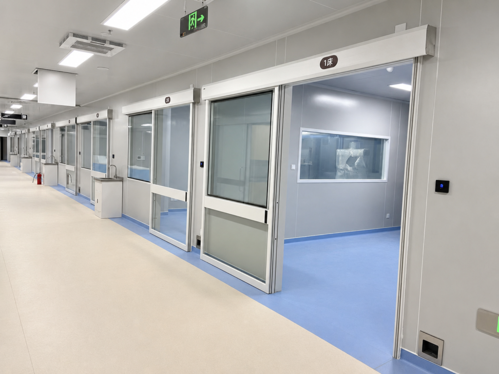
Several frame arrangements can be used, but each affects panel removal differently.
Wrap-around frame
A wrap-around frame covers the wall edges on both sides of the opening.
Potential advantages include:
- Clean coverage of panel edges
- Tolerance accommodation
- Strong visual definition around the opening
- Protection of vulnerable wall edges
Potential limitations include:
- Frame flanges may overlap removable panels.
- A panel may not move forward or sideways far enough to disengage.
- Frame removal may be required before adjacent panels can be replaced.
- The actual wall thickness must match the frame throat.
Split frame
A split frame uses separate components installed from opposite sides and connected through or around the wall.
Potential advantages include:
- Adjustment for wall-thickness variation
- Installation after wall construction
- Potential access to concealed fixings
Potential limitations include:
- More joints and components
- Potentially visible connections
- Dependence on accurate assembly and sealing
- Possible restriction of panel movement
Single-sided frame with separate closure trim
The main structural frame is positioned at the opening, while separate trims close the wall-panel edges.
This can make the interface more adaptable, particularly if the closure trim is removable. However, the trim must not be mistaken for structural support.
Flush frame
A flush frame aligns closely with the wall surface and can create a clean appearance.
Its concealed geometry remains important. A visually flush frame can still have hidden flanges, anchors, or backing plates that prevent panel removal.
No profile type automatically solves the interface. The decision should be based on the actual wall and maintenance strategy.
How Can Wall Panels Remain Removable Beside a Door Frame?
A panel can be described as independently removable only if it has enough movement to disengage from its fixings after the room is completed.
Depending on the system, removal may require the panel to:
- Lift vertically
- Move horizontally
- Pull directly forward
- Tilt away from the wall
- Follow a combined lifting and outward movement
The door frame must not block this path.
The design team should confirm:
- The direction of panel movement
- Minimum lifting clearance
- Clearance behind the frame flange
- Whether the perimeter gasket must be removed first
- Whether closure trims are individually removable
- Whether adjacent panels must be loosened
- Whether cables or equipment are fixed to the panel
- Whether the ceiling or floor closure restricts movement
In some projects, the panel immediately beside the door is intentionally fixed while the next panel remains removable. This can simplify the frame interface, but the fixed panel must be clearly identified on elevations and maintenance drawings.
A system should not claim that every wall panel is removable if the frame permanently traps the adjacent modules.
More information on panel access can be found in the removable operating theater wall panel guide.
How Much Frame Overlap Is Appropriate?
There is no universal frame-overlap dimension for modular operating theater walls.
The required overlap depends on:
- Frame profile
- Wall-panel edge design
- Structural opening tolerance
- Panel-removal direction
- Gasket or sealant geometry
- Appearance requirements
- Radiation shielding
- Fire-stopping details
- Installation sequence
A wide flange can conceal dimensional variation and protect the wall edge, but it may obstruct panel removal or create a deep ledge. A narrow flange may improve access but provide less coverage for site tolerances.
Drawings should distinguish between:
- Visible frame width
- Concealed flange depth
- Panel-edge engagement
- Nominal perimeter joint
- Sealant or gasket width
- Required removal clearance
The frame overlap should be determined from the complete interface section, not selected only for appearance.
How Should the Door Perimeter Be Sealed?
The exposed junction between the frame and wall should be smooth, cleanable, and compatible with expected movement.
Possible perimeter closures include:
- Elastomeric sealant
- Removable gasket
- Compressible tape behind a visible closure
- Snap-on or mechanically retained trim
- A combination of concealed seal and exposed gasket
- A manufacturer-specific frame seal
The selected detail should consider:
- Adhesion to the frame and wall finish
- Compatibility with powder coatings and stainless steel
- Expected differential movement
- Cleaning and disinfectant exposure
- Joint dimensions
- Replacement procedure
- Color stability
- Surface preparation
A thin decorative bead applied over an uncontrolled cavity should not be assumed to provide a durable environmental seal.
Where sealant is used, the joint geometry should allow suitable adhesion and movement. Where a removable gasket is used, the profile should remain retained without producing inaccessible dirt traps.
The perimeter seal does not carry the door. Structural anchorage and environmental sealing are separate functions.
How Should the Interface Connect with Three-Section Walls?
In a three-section wall, one or two horizontal joints may meet the vertical door frame.
The wall elevation should define whether each horizontal joint:
- Terminates against the frame
- Continues through a matching frame feature
- Is concealed behind a frame flange
- Connects to a separate perimeter gasket
- Changes level to avoid hardware
- Is locally sealed at the termination
The termination should not leave a short unrestrained gasket end. If horizontal gaskets stop against the frame, their end compression or connection method should be shown.
The frame can also divide the wall-panel grid. Narrow panel pieces beside the opening should be reviewed for:
- Fabrication feasibility
- Backing-board integrity
- Hook placement
- Flatness
- Handling
- Removal access
- Visual proportion
If possible, the door opening should be coordinated with the panel module during the elevation-design stage rather than placed after the panel grid is complete.
The three-section modular operating theater wall guide provides broader guidance on dividing the wall into upper, middle, and lower zones.
How Do Swing-Door Frames Affect the Wall Interface?
Swing doors transfer concentrated loads through hinges into the frame.
The interface must account for:
- Hinge position and fasteners
- Door-leaf weight
- Frame reinforcement
- Closer forces
- Latch and strike loads
- Door stops
- Repeated opening cycles
- Impact from beds or equipment
- Frame alignment
A heavy leaf can cause frame rotation or settlement if the support is inadequate. This can lead to uneven clearances, seal failure, latching problems, or contact between the leaf and floor.
The hinge jamb often requires greater reinforcement than the opposite jamb. Symmetrical frame appearance does not mean that both sides experience the same load.
If the wall panel covers the frame anchors, future hinge or frame adjustment may require removal of that panel. The design should ensure that the intended access remains possible.
How Do Sliding and Hermetic Door Frames Differ?
Sliding doors place important components above and beside the clear opening.
The design may need to coordinate:
- Head track
- Automatic operator
- Drive belt
- Rollers
- Control unit
- Sensors
- Emergency release
- Side frames
- Bottom guides
- Sealing surfaces
- Maintenance cover
A hermetic sliding door may move both horizontally and toward the frame or floor during closing, depending on the selected system. The wall interface must suit the manufacturer’s actual motion and sealing arrangement.
The head cover should be removable without dismantling the wall or ceiling unnecessarily. Power and control cables should be accessible through a defined service route.
The wall panel must not be used as the only support for the track unless the complete system has been engineered for that purpose.
If a sliding door is supplied separately from the modular wall package, the required structural opening, support, cable entry points, and finished wall face must be agreed before wall production.
How Should Door Services Be Routed?
Automatic and controlled doors can require:
- Power supply
- Operator control cables
- Activation switches
- Touchless sensors
- Safety sensors
- Access-control readers
- Interlocks
- Fire-alarm connections
- Status signals
- Emergency release devices
These services should not pass randomly behind removable panels.
The coordination drawings should show:
- Cable-entry points
- Conduit routes
- Junction boxes
- Maintenance access
- Separation from moving components
- Connection responsibility
- Interfaces with the hospital control system
A removable wall panel connected to short, fixed cables is not practically removable. Where equipment is mounted on a removable panel, connectors and cable slack should support the planned removal procedure.
Main building controls and complete HVAC control systems are not normally within JUXING’s supply scope, although interfaces with supplied doors and modular wall components can be coordinated from approved drawings.
How Should the Frame Meet the Floor?
The base of the frame must coordinate with the finished floor level and floor-cove detail.
Points requiring confirmation include:
- Frame termination height
- Floor finish thickness
- Cove radius
- Resin or vinyl upstand
- Threshold requirements
- Sliding-door guide position
- Seal contact
- Water and cleaning exposure
- Fixing access
The frame should not create an inaccessible pocket where the floor cove terminates.
For swing doors, an unnecessary raised threshold can obstruct beds and mobile equipment. However, threshold and seal requirements remain project-specific and may be influenced by acoustic, environmental, fire, or radiation considerations.
For sliding doors, the bottom guide and floor clearance must be coordinated with the finished floor—not only with the structural slab.
The floor installer needs the final frame detail before forming the cove.
How Should the Frame Meet the Ceiling?
Full-height frames or sliding-door head assemblies may extend to or above the finished ceiling.
The detail should address:
- Ceiling-panel termination
- Head-track support
- Access to operators and rollers
- Environmental sealing above the door
- Fire stopping where required
- Pressure leakage paths
- Above-ceiling wall continuity
- Removal of adjacent ceiling panels
A door frame reaching the ceiling should not be assumed to support the ceiling unless it has been specifically designed for that function.
Similarly, the suspended ceiling should not carry a heavy door track unless the structural system has been engineered accordingly.
The wall and ceiling interfaces should be reviewed together as part of the modular operating theater wall and ceiling system.
How Is Radiation Shielding Continued Around the Frame?
A radiation-protected door requires more than lead within the door leaf.
The shielding design may also involve:
- Lead lining within or behind the frame
- Shielding overlap at the jambs and head
- Continuity with wall shielding
- Treatment of fixing penetrations
- Threshold or floor details
- Vision panels
- Door hardware penetrations
- Cable and conduit routes
The required lead equivalence must be determined by a qualified radiation-protection specialist based on the imaging equipment, workload, room geometry, occupancy, and local requirements.
A door described as “2 mm Pb” does not automatically establish that the complete opening provides 2 mm lead equivalence. The frame, overlaps, wall transitions, observation windows, and penetrations must also be included in the shielding design.
Shielding layers should not block panel hooks or service access without an agreed removal strategy.
How Do Fire-Rated Doors Change the Interface?
A fire-resistance requirement applies to an approved or assessed door assembly, not only to the metal door leaf.
The relevant assembly may include:
- Door leaf
- Frame
- Hinges or track
- Closer
- Latch
- Seals
- Glazing
- Anchors
- Supporting wall construction
- Perimeter gap treatment
- Fire-stopping materials
Changing the frame profile, supporting wall, anchors, seals, or installation gap can affect the applicability of fire-performance evidence.
A stainless-steel or steel frame is not automatically fire-rated. Likewise, a non-combustible metal wall facing does not establish the fire resistance of the complete modular wall.
The project should identify the required fire classification and verify that the proposed door set, frame, wall construction, and installation method are compatible with the applicable evidence and local regulations.
How Does Frame Installation Sequence Affect the Result?
The installation sequence should be established before manufacturing.
Three common approaches are:
Frame before wall panels
The structural frame is installed and aligned first, followed by the adjacent wall panels and perimeter closures.
This can provide a stable opening datum but requires accurate panel dimensions and suitable edge details.
Frame after wall panels
The wall panels are installed first, and the frame wraps around or fits into the finished opening.
This can accommodate some site variation but may trap the panel edges and obstruct future removal.
Structural frame first, finish trims later
The support frame and door are installed in coordination with the wall structure, while removable closure trims are added after panel alignment.
This can separate structural support from visible finishing and may improve maintenance access.
No sequence is universally preferable. The correct approach depends on the door system, wall fixings, frame profile, and access strategy.
The approved installation method should state:
- Which component establishes the opening datum
- When frame anchors are tightened
- When panels are adjusted
- When seals and trims are installed
- How alignment is checked
- How future disassembly is performed
What Tolerances Should Be Controlled?
Door operation and panel appearance can both be affected by small dimensional errors.
The project should define tolerances for:
- Structural opening width and height
- Frame plumb and level
- Frame squareness
- Clear opening
- Wall thickness
- Finished-face position
- Panel-to-frame joint width
- Frame-face flushness
- Door-leaf clearances
- Floor level
- Sliding-track alignment
If the wall is thicker or thinner than expected, a wrap-around frame may not seat correctly. If the opening is not square, the frame may be distorted during fixing.
Sealant should not be used to conceal excessive construction error. Very large or varying joints can affect appearance, movement capacity, and long-term maintenance.
Adjustment zones should be included intentionally, with minimum and maximum limits.
How Should the Interface Be Inspected?
Inspection should cover concealed work before it is covered by panels or trims.
A practical sequence can include:
- Verify opening dimensions and supporting structure.
- Check frame reinforcement and anchorage.
- Confirm frame plumb, level, and squareness.
- Verify door operation before final closure.
- Inspect service routes and cable access.
- Inspect radiation shielding where applicable.
- Inspect fire stopping where required.
- Install and align adjacent wall panels.
- Check joint width and face flushness.
- Complete perimeter gaskets or sealant.
- Test door operation again.
- Demonstrate removal of a designated adjacent panel.
- Reinstall the panel and restore the perimeter closure.
- Complete specified enclosure and door-performance tests.
Photographs of concealed anchorage, shielding, and service routes can form part of the quality record.
What Should a Door-and-Wall Mock-Up Include?
A representative mock-up should use production-intent components rather than simplified display samples.
It may include:
- One complete frame jamb
- A representative frame head
- One adjacent removable wall panel
- Actual backing board
- Actual supporting steel
- Concealed hooks or clips
- Horizontal and vertical wall joints
- Perimeter gasket or sealant
- Floor-cove termination
- A representative cable route
- Radiation shielding where required
The mock-up should demonstrate:
- Panel installation
- Frame alignment
- Joint closure
- Door movement
- Panel removal
- Gasket or trim removal
- Access to frame fixings
- Reinstallation
- Final appearance
For heavy, automatic, radiation-protected, or project-specific doors, a full-scale prototype or factory assembly trial may be more useful than a small sectional sample.
What Should Be Included in the Tender Specification?
The tender documents should define responsibilities and interfaces clearly.
| Specification item | Information to include |
|---|---|
| Door schedule | Type, quantity, clear opening, operation, and handing |
| Door leaf | Material, thickness, weight, finish, and special functions |
| Frame | Profile, material, finish, throat, and overlap |
| Support | Structural frame and anchorage responsibility |
| Wall construction | Thickness, panel type, backing, and removability |
| Perimeter closure | Gasket, sealant, trim, or hybrid detail |
| Services | Power, controls, sensors, access, and cable routes |
| Radiation | Required design, lead equivalence, and continuity |
| Fire | Required classification and supporting evidence |
| Floor | Finished level, cove, threshold, and guide |
| Ceiling | Head closure, support, and maintenance access |
| Tolerances | Opening, alignment, joint, and flushness criteria |
| Mock-up | Required scale, components, and approval criteria |
| Maintenance | Panel-removal and door-service procedures |
| Documentation | Drawings, schedules, certificates, and inspection records |
Unclear responsibility at the frame perimeter can create gaps between the door supplier, wall supplier, structural contractor, radiation-shielding contractor, and electrical installer.
The project team should assign each interface task before procurement.
Buyer’s Checklist
Before approving the door-and-wall interface, confirm:
- Is the door type and operating method finalized?
- Are clear and structural opening dimensions distinguished?
- Is the frame throat matched to the completed wall thickness?
- Is the frame anchored to adequate structural support?
- Are door loads independent of the thin wall facing?
- Is the direction of adjacent panel removal shown?
- Do frame flanges obstruct panel movement?
- Are removable trims or gaskets identified?
- Are horizontal wall joints properly terminated at the frame?
- Are narrow panel pieces beside the opening manufacturable?
- Are automatic-door cables and controls accessible?
- Is the head track independently supported where required?
- Is the floor-cove termination detailed?
- Is the ceiling interface coordinated?
- Is radiation shielding continuous around the opening?
- Is the fire-rated door assembly compatible with the wall?
- Are tolerances and adjustment limits specified?
- Does the mock-up include panel removal and reinstatement?
- Are maintenance and spare-part requirements documented?
- Are supplier responsibilities clearly assigned?
Common Misconceptions
“The door frame can be screwed directly to the metal wall panel.”
The thin exposed facing is normally not the primary structural support for the door. Loads should transfer to suitable reinforcement or independent structure.
“A flush frame cannot obstruct panel removal.”
It can. Hidden flanges, anchors, and backing plates may still trap the panel.
“If the frame covers the gap, the interface is airtight.”
Visual coverage does not prove environmental sealing. The complete perimeter closure and other room leakage paths must be evaluated.
“A removable panel beside the door can always be lifted out.”
The frame, ceiling, floor, gaskets, or adjacent panels may block the required movement.
“A 2 mm Pb door provides 2 mm Pb protection around the complete opening.”
Not automatically. Shielding continuity depends on the frame, wall overlaps, penetrations, and specialist design.
“A steel frame is automatically fire-rated.”
No. Fire performance applies to the complete tested or assessed door assembly and supporting construction.
“Sealant can correct any opening tolerance.”
Excessive or inconsistent gaps should be corrected through coordinated construction, not concealed with uncontrolled sealant thickness.
Expert Tip
Ask the door and wall suppliers to produce one combined interface drawing rather than two separate drawings ending at the opening line.
The combined drawing should show the door leaf, frame, structural support, wall panel, backing board, concealed fixing, perimeter seal, removal clearance, floor finish, and any lead lining.
Then require a practical panel-removal demonstration on the mock-up. If the installer cannot remove and reinstall the designated panel without disturbing the frame, the interface is not independently removable in its proposed form.
Frequently Asked Questions
Should the door frame be installed before or after the wall panels?
Either sequence can work. The correct choice depends on the frame profile, panel-fixing method, structural support, and removal strategy. It should be defined before production.
Can a wrap-around frame be used with removable wall panels?
Yes, but its flanges must not block the required panel movement. Removable closure trims or a designated fixed panel may be necessary.
Can gypsum backing support a heavy operating theater door?
Ordinary gypsum backing alone should not be assumed to carry concentrated door loads. Suitable structural reinforcement is normally required.
Should the frame match the wall-panel finish?
It may match or intentionally contrast. The specification should define material, color, gloss, texture, and cleaning compatibility.
Can a gasket replace perimeter sealant?
A properly designed gasket may provide a removable closure, but suitability depends on the frame and wall geometry. It does not replace structural anchorage or automatically prove airtightness.
Are panels beside automatic sliding doors removable?
They can be, provided tracks, covers, cables, frame flanges, and service components do not obstruct removal. The procedure should be demonstrated.
Is a threshold required for an operating theater door?
Not universally. The decision depends on the door type, sealing method, fire or acoustic requirements, floor finish, and project specification. Unnecessary raised thresholds can obstruct mobile equipment.
Who should design radiation shielding around the frame?
A qualified radiation-protection specialist should determine the shielding requirement. The door and wall suppliers then coordinate fabrication with that design.
Does the door frame support the modular ceiling?
Not unless specifically engineered to do so. Door and ceiling supports should be defined independently.
What should be checked after removing and reinstalling a wall panel?
Check panel alignment, joint width, gasket or seal condition, frame clearance, door operation, surface damage, and any project-required enclosure performance.
Conclusion
Operating theater door frames must be designed as part of the wall system rather than inserted into an independently designed opening. Structural support, exposed finishing, perimeter sealing, panel removability, services, radiation protection, and fire requirements each need a defined solution.
For removable modular walls, the critical question is not whether the panel uses concealed hooks, but whether it can complete its required removal movement after the frame, floor, ceiling, gaskets, and door equipment are installed.
Coordinated interface drawings, representative mock-ups, and removal trials help prevent trapped panels, distorted frames, inaccessible services, broken sealing paths, and unsupported performance claims before full production begins.