
Introduction
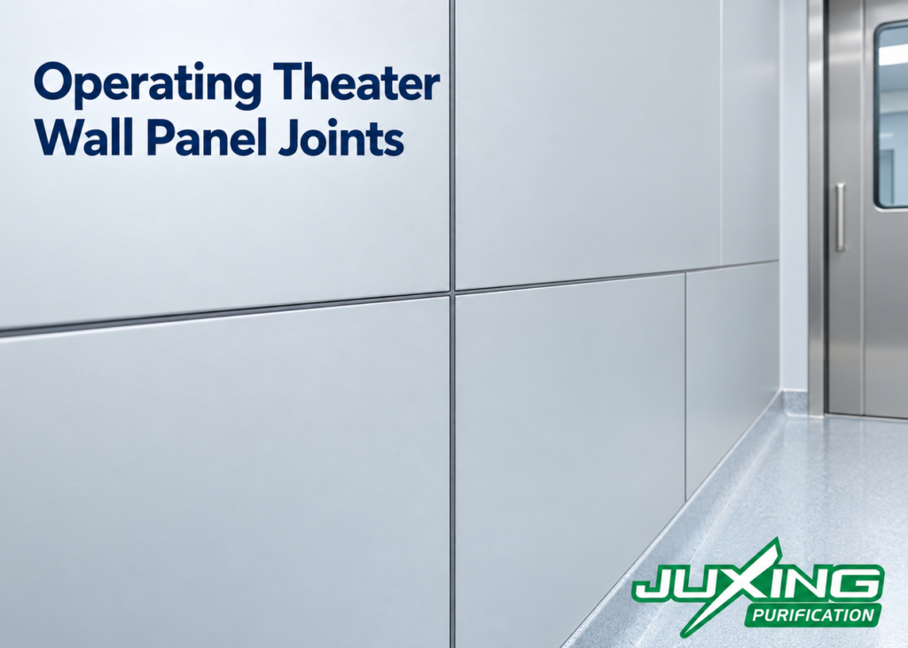
Operating theater wall panel joints become particularly difficult where horizontal and vertical joints meet. In a three-section modular wall, these intersections may occur at every vertical panel boundary, creating multiple T-shaped or cross-shaped details around the room.
A joint that performs well along a straight section may not remain continuous at an intersection. Gaskets can overlap, buckle, leave small gaps, or prevent one another from seating correctly. Sealant can become excessively thick, discontinuous, or difficult to replace. Dimensional variation in the panels can also accumulate at the same point.
These intersections therefore require dedicated drawings, production trials, and an agreed installation sequence. They should not be left for installers to resolve individually on site.
This article explains how horizontal and vertical joints can be coordinated in modular operating theater walls without assuming that a particular gasket, sealant, or joint profile automatically makes the complete room airtight.
Quick Answer
At a horizontal–vertical intersection, the designer must decide which joint remains continuous and how the second joint terminates against it.
Common strategies include:
- A continuous horizontal gasket with vertical gaskets terminating above and below it
- A continuous vertical gasket with horizontal gaskets terminating at each side
- A factory-formed intersection piece connecting both directions
- A mechanically retained gasket system with a locally sealed junction
- A continuous sealant joint formed after all wall panels are installed
- A hybrid arrangement combining removable gaskets and limited sealant at intersections
There is no universal detail suitable for every modular wall system. The correct solution depends on panel edges, gasket profile, groove geometry, installation sequence, removability requirements, manufacturing tolerances, cleaning needs, and the intended method of demonstrating enclosure performance.
Key Takeaways
- Straight joint details do not automatically resolve horizontal–vertical intersections.
- One sealing direction normally needs to take priority at each intersection.
- Overlapping two full-size gaskets can create excessive thickness or an unsealed corner.
- A visual cross does not prove that the seal is continuous behind the exposed surface.
- Horizontal and vertical joint widths must be coordinated before panel production.
- Panel tolerances accumulate at intersections and can affect gasket compression.
- Removable panels require an intersection detail that can be released without damaging adjacent panels.
- Local sealant may be used in some gasket systems, but this should be intentionally specified.
- Full-size mock-ups are more informative than separate samples of horizontal and vertical joints.
- Airtightness depends on the complete enclosure, not on wall joints alone.
Why Are Horizontal and Vertical Joint Intersections Difficult?
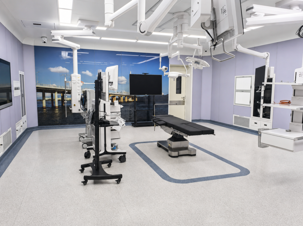
A straight gasket joint has a relatively simple sealing path. Two adjacent panel edges compress or retain one gasket along one direction.
At an intersection, several components meet:
- Two or four panel corners
- Horizontal and vertical grooves
- One or more gasket ends
- Folded metal edges
- Backing boards
- Hooks or concealed fixings
- Manufacturing tolerances
- Installation clearances
If both gaskets continue through the same plane without modification, their combined thickness may prevent one gasket from seating correctly. Cutting both gaskets at the center can avoid overlapping, but it may create a small opening exactly where the four panel corners meet.
The challenge is not merely cosmetic. The detail should provide:
- A continuous and cleanable exposed surface
- Controlled gasket compression or sealant geometry
- A practical installation sequence
- Compatibility with panel movement
- Access for future panel removal where required
- Repeatable factory and site workmanship
A neat visible joint can conceal a discontinuity behind the exposed surface. Conversely, a small visible joint line does not necessarily mean that the assembly is leaking. Performance must be assessed using the actual system design and appropriate project testing.
What Types of Joint Intersection Occur in Modular Walls?
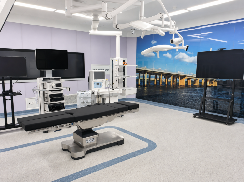
Three-section wall systems commonly create several intersection types.
| Intersection type | Typical location | Main coordination issue |
|---|---|---|
| Four-way cross | Vertical boundary between panels crossing a continuous horizontal joint | Four panel corners and two joint directions meet |
| Left-facing T-joint | Horizontal joint terminates at a full-height panel | Terminating the horizontal gasket without leaving a gap |
| Right-facing T-joint | Opposite end of a horizontal panel zone | Mirrored geometry and installation sequence |
| Upward T-joint | Vertical joint terminates at a horizontal joint | Compression and closure at the gasket end |
| Downward T-joint | Vertical joint begins below a horizontal joint | Alignment between upper and lower panel modules |
| Offset intersection | Upper and lower vertical joints do not align | Horizontal gasket continuity and appearance |
| Joint-to-frame intersection | Horizontal joint meets a door, window, or cabinet frame | Transition between wall seal and frame perimeter seal |
| Joint-to-corner intersection | Horizontal joint meets an internal or external corner | Continuity around corner trims or formed panels |
Not every three-section wall needs vertically aligned panel boundaries. Staggering upper and lower vertical joints can reduce the number of four-way intersections, but it may complicate manufacturing, panel numbering, appearance, and future replacement.
The layout should therefore be chosen intentionally rather than altered during installation.
How Should Operating Theater Wall Panel Joints Intersect?
Operating theater wall panel joints should intersect according to a predefined hierarchy. The design team should decide which sealing path remains continuous and which gasket or seal terminates against it.
Continuous horizontal gasket
In this arrangement, the horizontal gasket runs around the wall without interruption where practical. Vertical gaskets above and below it terminate against the horizontal gasket.
Potential advantages include:
- A visually continuous horizontal equipment-band line
- Consistent separation between the three wall sections
- Easier coordination where middle panels are intended for equipment access
- Fewer joints in the continuous horizontal gasket
Points requiring attention include:
- The ends of the vertical gaskets must seal against the horizontal gasket.
- Upper and lower vertical joints must remain aligned where the design requires alignment.
- Gasket-end geometry must not create a small triangular opening.
- Removing a middle panel must not damage the continuous gasket.
Continuous vertical gasket
Here, the vertical gasket passes through the horizontal joint while the horizontal gaskets terminate on each side.
This may suit systems in which full-height vertical sealing paths or removable vertical modules are prioritized. However, it can interrupt the appearance and continuity of the horizontal equipment band.
Factory-formed intersection component
A molded or fabricated cross or T-piece can connect the joint directions. This may improve repeatability if the component matches the gasket profile and groove geometry.
It also introduces additional considerations:
- Tooling or mold cost
- Minimum order quantity
- Dimensional compatibility
- Material and color matching
- Cleaning geometry
- Availability of spare parts
- Replacement procedure
A custom intersection component should be validated as part of the actual wall system. Its existence alone does not prove airtightness.
Locally sealed intersection
Some removable gasket systems use a small, controlled amount of compatible sealant at the intersection. This can close the interface between gasket ends while retaining removability along most of the joint length.
This is a hybrid joint, not a completely sealant-free system. The drawings and maintenance instructions should state where the local sealant is applied and how it is removed and reinstated.
Should Horizontal and Vertical Joints Be Aligned?
Alignment often creates a clean and disciplined appearance, particularly in three-section walls. It can also simplify panel schedules because upper, middle, and lower panel widths share the same grid.
However, alignment produces four-way intersections that require careful detailing.
Offsetting the vertical joints can replace a four-way cross with separate T-joints. This may simplify sealing at an individual location, but it can introduce other issues:
- More panel sizes
- Less visual symmetry
- More complicated production drawings
- Greater risk of incorrect panel positioning
- Different removal sequences
- Additional panel identification requirements
Neither arrangement is automatically superior.
The decision should consider wall elevation, equipment positions, doors, cabinets, medical gas outlets, control panels, access requirements, and the selected joint system.
The three-section modular operating theater wall guide explains how panel zones can be coordinated before individual intersections are developed.
How Do Gasket Profile and Groove Geometry Affect the Intersection?
A gasket and its retaining groove must be evaluated together. The exposed gasket width alone does not define the connection.
Relevant profile characteristics include:
- Gasket material
- Cross-sectional shape
- Compression range
- Retaining barbs or legs
- Direction of insertion
- Groove depth and width
- Permitted stretch
- Corner-forming behavior
- Resistance to cleaning chemicals
- Replacement method
A profile designed for a straight joint may not turn through 90 degrees or form a reliable cross without a molded fitting.
Installers should not be expected to stretch, notch, or cut a gasket in an undefined manner. Excessive stretching can reduce the gasket cross-section and cause later shrinkage. Poorly controlled notching can damage the retaining portion or create an opening.
Groove intersections also need a production detail. Simply machining or folding two grooves across one another can create:
- Excessive cavity depth
- Unsupported gasket sections
- Sharp edges
- Coating buildup
- Inconsistent gasket retention
- A visible depression at the crossing
The joint manufacturer should provide a dimensioned cross-section and an intersection detail, not only a sample of the straight gasket.
How Should Gasket Ends Be Terminated?
The end of a vertical or horizontal gasket is a critical sealing point.
Possible termination methods include:
- Square-cut end compressed against the continuous gasket
- Shaped end matching the opposing gasket profile
- Factory-vulcanized or molded termination
- Mechanical end retainer
- Local application of compatible sealant
- Dedicated T-shaped connection piece
A square cut is simple, but it is effective only if the mating geometry provides controlled contact. If the gasket end merely touches another exposed surface without compression, a small gap may remain.
The end should not be cut too short and then stretched into position. Gasket recovery or temperature changes may cause it to retract later.
The design should specify whether gaskets are installed:
- At their natural length
- With controlled compression
- With a permitted amount of stretch
- With sealed or mechanically retained ends
These instructions must come from the system or gasket design rather than being assumed on site.
What Joint Width Should Be Specified?
There is no internationally mandatory joint width for modular operating theater wall panels.
The required width depends on:
- Gasket cross-section
- Groove design
- Panel-edge returns
- Installation adjustment
- Manufacturing tolerance
- Thermal and building movement
- Coating thickness
- Removal clearance
- Desired appearance
A narrow visible joint may appear attractive but can be sensitive to panel-size variation. A wider joint may provide more tolerance while making alignment errors more visible.
The drawing should distinguish among:
- Nominal panel-to-panel gap
- Exposed gasket width
- Groove width
- Minimum and maximum acceptable installed gap
- Permitted variation along the joint
These dimensions are related but are not necessarily identical.
Project teams should avoid treating a supplier’s standard groove dimension as an ISO, EN, or HTM requirement unless a relevant document explicitly states it.
How Do Manufacturing Tolerances Accumulate at a Cross Joint?
At a four-way intersection, the dimensions of four panel corners influence one visible point.
Potential sources of variation include:
- Sheet cutting
- Folding
- Backing-board cutting
- Adhesive thickness
- Edge-return dimensions
- Coating thickness
- Hook position
- Supporting-frame alignment
- Site datum accuracy
- Panel installation sequence
Small deviations that are acceptable along a single edge can combine to produce a noticeable step or uneven cross.
The tolerance plan should address:
- Panel width and height
- Squareness
- Diagonal difference
- Edge straightness
- Joint-width variation
- Flushness between adjacent faces
- Alignment of upper and lower vertical joints
- Alignment of the horizontal joint around corners
A panel should not be forced into position by excessive gasket compression. This can transfer stress to the panel facing, backing, hooks, or adjacent modules.
How Should the Installation Sequence Be Planned?
Joint performance often depends on the order in which panels and gaskets are installed.
A typical sequence may include:
- Establish room datums and verify the supporting frame.
- Install and align the lower wall panels.
- Check the first horizontal joint elevation.
- Install the middle panel zone and coordinate equipment openings.
- Check the second horizontal joint elevation.
- Install the upper panels.
- Adjust face alignment and joint widths.
- Install continuous priority gaskets.
- Cut and install terminating gaskets.
- Complete defined intersection sealing or connection pieces.
- Inspect the completed intersections.
- Test representative panels for removal and reinstatement.
The actual sequence may differ for rear-hook, clip-fixed, or front-access systems.
If the gasket must be inserted before the next panel is installed, replacement may require dismantling adjacent elements. That detail should not be described as readily replaceable unless the replacement procedure has been demonstrated.
The removable operating theater wall panel guide provides further guidance on access and removal planning.
How Can Panels Remain Removable at Joint Intersections?
Panel removability depends on more than concealed hooks.
At an intersection, removal can be restricted by:
- A continuous gasket crossing the removable panel edge
- Bonded intersection pieces
- Sealant connecting multiple panel corners
- Overlapping trims
- Adjacent cabinet or door frames
- Insufficient lifting or lateral movement
- Ceiling or floor closures
- Service connections behind the panel
The design should identify which panels are intended to be removable and in which direction they move.
A practical removal trial should answer:
- Which gasket is removed first?
- Can it be extracted without cutting?
- Does removing one gasket release several panels?
- Is a suction tool or lifting handle required?
- Can the panel clear its hooks?
- Must adjacent panels be loosened?
- How is the intersection resealed afterward?
- Are replacement gaskets or local sealants required?
“Demountable” should not be used as a general marketing term without a defined procedure and access condition.
How Should Joints Meet Doors, Windows, and Cabinets?
AA horizontal wall joint may meet a door frame, observation window, built-in cabinet, control panel, or medical gas box.
At each interface, the drawings should show whether the joint:
- Continues across the frame
- Terminates against the frame
- Changes height
- Is concealed behind a flange
- Connects to a separate perimeter gasket
- Uses a local sealant transition
Misalignment can produce short pieces of gasket, narrow metal strips, or small surfaces that are difficult to fabricate and clean.
The wall elevation should therefore coordinate horizontal joint heights with:
- Door head heights
- Window sill and head levels
- Cabinet edges
- Equipment-band openings
- Medical gas terminal positions
- Electrical outlets and control panels
A nominally standardized middle zone may need adjustment when openings have already been fixed by medical equipment requirements. The design should resolve these conflicts before production.
How Should Intersections Be Detailed at Internal and External Corners?
Horizontal joints normally continue around room corners, but the sealing method may change.
Possible corner arrangements include:
- Folded one-piece metal corner panels
- Separate radiused corner profiles
- Gasketed corner connections
- Sealant-finished corners
- Fabricated stainless-steel closures
The horizontal gasket may:
- Continue through a compatible corner groove
- Terminate against a corner profile
- Connect to a molded corner fitting
- Be locally sealed at the corner
Corners must also accommodate site geometry. An internal corner that is not square can alter the final panel width and move the nearest joint intersection.
Corner closure pieces should not be used to conceal large dimensional errors without reviewing their effect on cleanability, removability, and appearance.
Should Sealant or Removable Gaskets Be Used at Intersections?
Both approaches can be suitable when correctly designed.
| Evaluation point | Removable gasket intersection | Sealant intersection |
|---|---|---|
| Future replacement | Potentially convenient if the system is accessible | Normally requires cutting and reapplication |
| Factory repeatability | Depends on accurate profiles and fittings | Depends on joint dimensions and application procedure |
| Site workmanship | Correct insertion and termination are critical | Surface preparation, masking, tooling, and curing are critical |
| Movement accommodation | Depends on gasket geometry and compression | Depends on sealant type and joint design |
| Visual consistency | Controlled by profile and alignment | Controlled by tooling and installer skill |
| Complex cross details | May require molded parts or local sealant | Can accommodate irregular geometry more readily |
| Maintenance | Gaskets may be extracted and replaced | Damaged sealant must be removed and renewed |
| Claim of complete removability | Must be demonstrated | Generally limited where continuous sealant bonds panels |
A hybrid design may be the most practical solution in some systems. For example, long joints can use replaceable gaskets while a small amount of compatible sealant closes the intersection.
If a hybrid method is used, it should be disclosed in the technical submission and reflected in maintenance instructions.
How Should Airtightness Be Evaluated?
A gasketed intersection should not be described as airtight solely because it looks closed.
Possible evaluation methods include:
- Visual inspection
- Controlled local smoke tracing
- Local leakage assessment
- Room pressure-decay testing
- Whole-room air-leakage testing
- Operational pressure verification
The method and acceptance criteria should be defined by the project specification and applicable local requirements.
Room pressurization results reflect the complete enclosure, including:
- Wall joints
- Door seals
- Window perimeters
- Ceiling joints
- Floor junctions
- Medical gas penetrations
- Electrical outlets
- Cabinets
- Access panels
- Service openings
A room can maintain positive pressure while still having leakage at individual wall intersections. Conversely, a well-sealed wall intersection cannot compensate for major leakage elsewhere.
The complete wall construction should also be coordinated with the modular operating theater wall and ceiling system.
What Should Be Checked During a Mock-Up?
A full-size mock-up should include more than two straight panel edges.
For a three-section system, the sample should preferably contain:
- One four-way cross intersection
- One T-intersection
- Upper, middle, and lower panels
- The actual gasket and groove profiles
- Production coating or surface finish
- Actual backing material
- Rear hooks or concealed fixings
- One representative equipment opening
- One corner or frame interface where practical
The mock-up should be used to evaluate:
- Joint continuity
- Gasket compression
- Gasket-end treatment
- Surface flushness
- Horizontal alignment
- Vertical alignment
- Cleanability
- Panel removal
- Gasket replacement
- Reassembly
- Appearance under representative lighting
A mock-up is a design-verification tool. It does not, by itself, certify the complete project installation or replace final room testing.
What Should Production Drawings Show?
Production drawings should communicate the detail clearly enough for both factory workers and site installers.
They should identify:
- Panel numbers
- Panel dimensions
- Upper, middle, and lower zones
- Horizontal and vertical joint widths
- Joint priority at every intersection
- Gasket profile codes
- Gasket installation direction
- Gasket termination details
- Molded T- or cross-pieces
- Locations of any permitted sealant
- Hook and fixing positions
- Door, window, and cabinet interfaces
- Panel removal direction
- Installation sequence
- Inspection points
An elevation showing joint lines is not sufficient. At least one enlarged section or axonometric detail should show what occurs behind the visible crossing.
Where several intersection types exist, each type should receive a detail code that can be referenced from the wall elevations.
Buyer’s Checklist
Before approving operating theater wall panel joints, confirm:
- Has every T- and cross-intersection type been identified?
- Is the continuous sealing direction defined?
- Are gasket ends shown in enlarged details?
- Is the gasket profile suitable for the proposed intersection?
- Are molded intersection pieces required?
- Are these components included in the supply quantity?
- Are spare gaskets and fittings included?
- Is local sealant used anywhere in the gasket system?
- Are coating thickness and groove dimensions coordinated?
- Are nominal joint widths and permitted variations specified?
- Are panel tolerances and face-flushness criteria defined?
- Is the installation sequence documented?
- Can the designated panels actually be removed?
- Has removal and reinstatement been demonstrated?
- Are door, window, cabinet, and corner interfaces detailed?
- Does the mock-up include a real cross intersection?
- Is the project’s enclosure testing method defined?
- Are cleaning and replacement instructions included?
Common Misconceptions
“If both straight gasket joints work, their intersection will work.”
Not necessarily. Overlap, termination, compression, and groove geometry must be resolved separately.
“Two gaskets can simply cross over each other.”
They may create excessive thickness, distortion, or a hidden gap. The intersection needs a designed geometry.
“A visible cross means the seal is continuous.”
No. The exposed joint pattern does not show what happens behind the surface.
“Narrower joints are always more hygienic.”
Not automatically. An excessively narrow joint may prevent proper gasket seating and make manufacturing variation harder to control.
“A removable gasket makes every panel independently removable.”
Panel removal may still be blocked by crossing gaskets, trims, frames, ceilings, or the fixing direction.
“Positive room pressure proves that every joint is airtight.”
No. Room pressure is a system-level condition and does not identify leakage at individual intersections.
“A custom gasket profile automatically complies with ISO 14644 or HTM requirements.”
No. A profile is a manufacturer’s component. Compliance or conformity must be evaluated for the applicable project, complete system, test method, and governing requirements.
Expert Tip
Make the first production trial a four-panel intersection rather than a single straight joint.
Use actual panel edges, backing, coating, gaskets, hooks, and groove dimensions. Install the sample in the intended sequence, photograph the hidden stages, remove one designated panel, and then reinstall it.
This simple trial often reveals interference, gasket shrinkage, incorrect cutting instructions, insufficient removal clearance, and tolerance problems before an entire room is manufactured.
Frequently Asked Questions
What is the best orientation for a continuous gasket?
There is no universal answer. A continuous horizontal gasket often suits three-section equipment-band walls, while a continuous vertical gasket may suit other panel layouts. The decision should reflect removability and installation sequence.
Can horizontal and vertical gaskets be cut at 45 degrees?
A mitered cut may be possible for a suitable profile, but it should not be assumed to seal correctly. The geometry, compression, and cutting tolerance must be tested.
Is a molded cross-piece always necessary?
No. Some systems use shaped gasket ends or limited sealant. A molded component is one option when it provides a repeatable and maintainable detail.
Can sealant be used only at the intersection?
Yes, if it is compatible with the gasket, coating, cleaning regime, and maintenance procedure. The system should then be described as a hybrid detail.
Should upper and lower vertical joints align?
They may align for appearance and standardization, but this creates four-way intersections. Offset joints are another option and create different fabrication and installation requirements.
How much gasket compression is required?
The required compression depends on the specific gasket profile and system design. It should be obtained from the gasket or system engineering data rather than assumed as a universal percentage.
Can installers cut the gasket to suit site conditions?
Final trimming may be necessary, but the cutting and termination method should be documented. Uncontrolled stretching or improvised notching should be avoided.
How can gasket shrinkage be reduced?
Use suitable material, store it correctly, install it according to the specified temperature and tension conditions, and avoid excessive stretching. The gasket supplier should provide relevant installation guidance.
Does every joint intersection need individual leakage testing?
Not necessarily. The project quality plan should define representative inspections, mock-up testing, and whole-enclosure testing. Critical or unusual intersections may warrant additional checks.
Conclusion
Operating theater wall panel joints require dedicated engineering where horizontal and vertical lines intersect. The most important decisions are which seal remains continuous, how terminating gaskets connect to it, how tolerances are controlled, and whether the completed panels remain removable.
A successful detail should be cleanable, repeatable, inspectable, and compatible with the intended installation and maintenance sequence. It should also be shown in enlarged production drawings and verified through a representative four-panel mock-up.
Even a well-designed intersection does not independently establish room airtightness or compliance. Final performance depends on the complete operating theater enclosure, including walls, ceilings, floors, doors, windows, cabinets, and every service penetration.