
Introduction
Modular operating theater walls must accommodate doors, observation windows, medical-gas outlets, electrical sockets, control panels, built-in cabinets, return-air grilles, protective finishes, and maintenance access. Although the finished enclosure may appear simple, coordinating these components requires detailed planning before panel production begins.
When these components are distributed across full-height wall panels without a clear organizing principle, coordination becomes difficult. A modification to one service outlet may require remanufacturing a large panel, while future maintenance can disrupt adjacent finishes.
A three-section wall design divides the operating theater wall vertically into lower, middle, and upper zones. The middle section commonly functions as an equipment or service band, while the lower and upper sections complete the hygienic enclosure.
This arrangement can improve coordination, prefabrication, replacement, and visual organization. However, it is not a universal requirement, and it does not automatically make a wall compliant, airtight, fire-resistant, or easier to maintain. Its success depends on the complete wall construction and the detailed treatment of every interface.
Quick Answer
A three-section modular operating theater wall normally consists of:
- A lower wall section extending from the floor junction to the equipment band
- A middle service section containing selected wall-mounted or built-in components
- An upper wall section extending from the service band to the ceiling junction
The exact heights are project-specific. A horizontal division at approximately 1.0–1.2 m above finished floor level may be used in some modular systems, but it is not an ISO-mandated or universally standardized dimension.
The design is most effective when the horizontal joints align with doors, cabinets, control panels, medical-gas outlets, electrical services, return-air grilles, and the internal support structure. Poorly coordinated horizontal and vertical joints may instead create difficult intersections, narrow infill pieces, cleaning concerns, and installation problems.
Key Takeaways
- Three-section wall construction is a modular design strategy, not an international regulatory requirement.
- The middle section can organize services and built-in components into a coordinated horizontal band.
- Section heights should be established from clinical use, equipment dimensions, accessibility requirements, and approved drawings.
- Horizontal joints should be coordinated with vertical panel joints before production begins.
- Built-in equipment must have suitable framing and support; the finish panel should not be treated as a structural support.
- The design must consider cleaning, air leakage, fire stopping, radiation shielding, and maintenance access as separate performance issues.
- Doors, observation windows, cabinets, and return-air grilles should be treated as complete interface assemblies.
- Full-scale mock-ups can identify alignment and installation problems before mass production.
- Panel dimensions should reflect manufacturing capability, transport limits, site access, and replacement strategy.
- Final compliance depends on the complete installed system and project-specific verification.
How Are Three-Section Modular Operating Theater Walls Designed?
A three-section modular wall divides the visible wall surface into three horizontal zones.
| Wall zone | Typical function | Common coordination items |
|---|---|---|
| Upper section | Completes the enclosure above the service band | Ceiling junctions, upper door frames, observation windows, signage, high-level services |
| Middle section | Organizes frequently used services and equipment | Medical-gas outlets, electrical sockets, control panels, clocks, writing desks, built-in cabinets |
| Lower section | Protects the lower wall and connects to the floor | Impact protection, low-level return grilles, floor coving, skirting details, maintenance access where specified |
The word “three-section” describes the visual and construction arrangement. It does not prescribe a particular wall material, panel thickness, frame type, joint profile, or fixing method.
The three sections may use the same surface material, such as coated steel or stainless steel, or different compatible finishes where the project permits. They may also use removable panels, mechanically fixed panels, bonded panels, or a combination of systems.
For an overview of the wider enclosure options, see modular operating theater wall and ceiling systems.
Why Use Three Horizontal Wall Sections?
The main purpose is to organize the wall around clinical equipment and building services.
In a full-height panel system, an outlet or cabinet opening may occur anywhere within a large panel. Each opening must be accurately positioned, reinforced, manufactured, packed, delivered, and installed. A late change can affect the entire panel.
A separate middle service band can provide several practical advantages:
- Repeated equipment positions can be standardized across similar rooms.
- Service penetrations can be concentrated within a controlled zone.
- Smaller sections may be replaced without removing a full-height panel.
- Built-in cabinets and control panels can align with surrounding joints.
- Installation teams can identify service zones more easily.
- Future changes may affect fewer components.
- The wall elevation can appear more orderly and intentional.
These advantages are only achieved when the architectural, mechanical, electrical, medical-gas, and equipment drawings use the same coordinated dimensions.
Adding horizontal joints without coordinated planning merely increases the number of interfaces requiring manufacture, sealing, cleaning, and inspection.
Are the Three Section Heights Standardized?
No universal international standard prescribes one set of heights for three-section operating theater walls.
A project may establish the equipment band at approximately 1.2 m above the finished floor, but that value should be treated as a project or manufacturer dimension—not an ISO, HTM, or EN requirement unless explicitly stated in the applicable project specification.
The final section heights should consider:
- Medical staff reach and usability
- Accessibility requirements
- Medical-gas outlet positions
- Electrical and data outlet positions
- Operating theater control-panel dimensions
- Built-in cabinet and writing-desk heights
- Door-frame geometry
- Observation-window dimensions
- Return-air grille positions
- Mobile equipment and trolley impact zones
- Structural framing locations
- Floor and ceiling build-up
- Local healthcare design guidance
Dimensions should always reference the finished floor level, not the unfinished structural slab.
The design team must also define whether the stated height refers to the joint centerline, visible panel edge, equipment centerline, or top of the middle section. Unclear dimensioning can create misalignment between factory-produced panels and site-installed services.
How Should the Middle Service Band Be Designed?
The service band should begin with a coordinated equipment schedule rather than an arbitrary horizontal line.
For each wall elevation, the designer should identify:
- Equipment type
- Manufacturer and model, where available
- Overall dimensions
- Required opening size
- Mounting height
- Recess depth
- Maintenance clearance
- Cable, pipe, or duct entry direction
- Structural support requirement
- Access-panel requirement
- Fire-stopping requirement
- Radiation-shielding requirement, where applicable
- Responsibility for supply and installation
Typical items within the service band may include:
- Medical-gas terminal units
- Electrical sockets
- Equipotential bonding points
- Data outlets
- Operating theater control panels
- Time displays and surgical timers
- Nurse-call components
- Writing desks
- X-ray viewers or medical displays
- Built-in medicine, instrument, and anesthesia cabinets
- Touchless controls
- Selected return-air grilles
Not every item should automatically be placed in the service band. Its location must support clinical use, equipment manufacturer instructions, infection-control requirements, and the applicable electrical and medical-gas regulations.
JUXING can coordinate wall panels with selected built-in components as part of its operating room systems supply scope. Final service layouts should nevertheless be approved by the responsible project consultants and specialist contractors.
How Should Horizontal and Vertical Joints Intersect?
The intersection between a horizontal section joint and a vertical panel joint is one of the most important details in this wall system.
A poorly designed crossing can create:
- Discontinuous seals
- Uneven joint widths
- Visible misalignment
- Small gaps at the intersection
- Dirt-retaining recesses
- Difficulty inserting or replacing gaskets
- Local stress or panel distortion
- Unclear installation sequencing
The design team should decide whether the joint pattern will use:
- Continuous horizontal joints crossing the vertical joints
- Continuous vertical joints crossing the horizontal divisions
- Coordinated four-way intersections
- Staggered joints that avoid four-way intersections
Each method has implications for appearance, sealing, fabrication, and replacement.
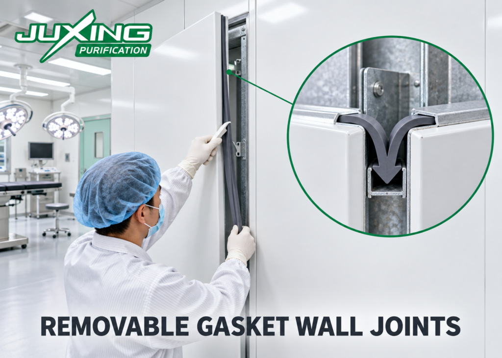
Where removable gaskets are used, the drawings should define:
- Which gasket runs continuously
- Where each gasket terminates
- Whether the gasket is replaced horizontally or vertically
- How the intersection is sealed
- Required insertion and removal clearance
- Acceptable joint-width tolerance
- Treatment of cut gasket ends
- Installation order
A removable gasket is a maintainable joint component, but it does not independently prove that the wall or room is airtight. Air leakage must be evaluated across the complete enclosure, including corners, doors, windows, floor junctions, ceilings, and service penetrations.
How Are Built-In Cabinets Integrated into the Three-Section Wall?
Built-in cabinets should be treated as framed wall openings, not simply as boxes inserted through finish panels.
The cabinet interface normally requires coordination of:
- Rough opening dimensions
- Finished opening dimensions
- Cabinet flange or trim
- Wall-frame reinforcement
- Cabinet depth
- Rear access requirements
- Flushness with the wall surface
- Joint positions
- Sealant or gasket details
- Load transfer
- Cleaning access
- Fire and acoustic requirements
- Radiation protection, where applicable
The cabinet and its contents may impose loads that the finish panel cannot safely carry. Where necessary, the cabinet should be supported by the wall frame, floor, or another independently designed support system.
Horizontal joints should preferably align with a logical cabinet edge rather than passing through a flange, hinge, handle, or maintenance opening. Narrow panel strips around cabinets should be avoided because they can be difficult to fabricate, align, and secure.
If a cabinet needs replacement, the removal route should be established during design. A theoretically removable cabinet provides little benefit if adjacent panels, medical-gas lines, or permanent trims prevent it from being withdrawn.
How Should Door Frames Connect to the Three Wall Sections?
Door openings often extend through all three wall zones and therefore interrupt both horizontal and vertical panel joints.
The door-frame detail should clarify:
- Frame anchorage
- Structural support around the opening
- Connection to the modular wall frame
- Panel termination at the jamb and head
- Joint width around the frame
- Sealing method
- Finished surface alignment
- Threshold or floor interface
- Automatic-door wiring and access
- Radiation shielding continuity, if required
- Fire-rating requirements, if applicable
- Replacement and maintenance access
The door frame should not rely solely on thin finish panels for stability. Repeated door movement, closer forces, automatic operators, and accidental impacts can transfer significant loads into the opening.
For radiation-protected doors, the lead equivalence cannot be selected from the wall arrangement alone. A qualified radiation-protection specialist should determine the shielding requirements from the imaging equipment, radiation source, workload, orientation, occupancy, and surrounding construction.
Shielding continuity at the frame, door leaf, observation panel, penetrations, and adjacent wall construction must be detailed as a complete system.
How Should Observation Windows Be Coordinated?
Observation windows may cross one or more horizontal sections. The design should determine whether the window:
- Fits entirely within the middle or upper section
- Aligns with a horizontal joint
- Interrupts a horizontal joint
- Requires multiple surrounding panel pieces
- Includes radiation-protective glazing
- Requires a flush frame on one or both sides
The window frame should be coordinated with the wall thickness and selected panel construction. The detail should avoid exposed ledges and difficult-to-clean recesses on the operating-theater side.
Where lead-lined glazing is required, both the required lead equivalence and the visual field must be specified. The interface between the glass, frame, and surrounding wall shielding must maintain the shielding design without unsupported gaps.
Radiation performance should be verified through appropriate documentation and, where required, site testing by qualified personnel.
How Are Medical-Gas and Electrical Services Coordinated?
The three-section wall system organizes visible outlets, but it does not replace specialist service design.
Medical-gas systems should be designed, installed, tested, and certified according to the applicable national requirements and approved project specifications. Electrical systems should similarly follow the regulations for medical locations in the project jurisdiction.
Before wall-panel production, a coordinated elevation should identify:
- Outlet centerlines
- Cutout sizes
- Mounting boxes
- Pipe and cable routes
- Separation between different services
- Access for testing and maintenance
- Equipment identification
- Future spare capacity
- Panel removal restrictions
Services behind a removable panel should include sufficient flexibility, isolation, or accessible disconnection arrangements where removal is expected. A panel should not be described as independently removable if fixed pipes, short cables, or inaccessible connections prevent safe removal.
Uncontrolled site cutting should be minimized. Openings produced after coating may expose raw edges, damage protective finishes, introduce metal debris, and bypass the intended reinforcement arrangement.
What Backing and Framing Can Be Used Behind the Panels?
The visible metal panel is only one component of the wall assembly.
Depending on the selected system, the wall may include:
- Coated steel or stainless-steel facing
- Folded panel edges
- Gypsum-based backing board
- Other approved noncombustible or composite backing materials
- Galvanized steel framing
- Rear hooks or adjustable fixing brackets
- Insulation or acoustic infill
- Service cavities
- Joint gaskets or sealants
- Fire stopping
- Reinforcement around openings
Backing-board thicknesses such as 12 mm, 15 mm, or 18 mm may be specified, but thickness alone does not establish the board’s strength, fire performance, moisture behavior, or suitability.
The board type, density, edge condition, fixing spacing, moisture resistance, dimensional tolerance, fire classification, and compatibility with adhesives or metal facings should all be reviewed.
Similarly, a metal surface does not make the complete wall assembly fire-resistant. Any required fire performance must be demonstrated for the complete construction, including boards, framing, insulation, adhesives, joints, openings, penetrations, and perimeter seals.
Can Each Wall Section Be Removed Independently?
It can be designed that way, but the word “removable” requires a precise definition.
A section may be:
- Demountable using standard tools
- Removable only after adjacent trims are taken off
- Replaceable after removing another panel
- Accessible only from the rear
- Removable without disturbing services
- Removable only after services are isolated
- Intended for occasional replacement rather than routine access
The project specification should state the required level of removability.
Rear-hook or adjustable fixing systems may allow panels to be aligned and removed with less damage than permanently bonded systems. However, removal still depends on joint details, surrounding components, installation sequence, available clearance, panel weight, and service connections.
The operation should be demonstrated on a mock-up where future panel replacement is an important procurement requirement.
How Does the Three-Section Design Affect Cleaning?
A modular joint should be narrow, consistent, durable, and compatible with the hospital’s cleaning process.
The wall surface and joint materials should be assessed for:
- Resistance to specified cleaning chemicals
- Repeated wiping and disinfection
- Surface staining
- Corrosion
- Gasket swelling or shrinkage
- Cracking or loss of elasticity
- Joint recess depth
- Dirt retention
- Repairability
- Replacement availability
More joints do not automatically make a wall unhygienic. Properly designed, flush, and maintainable joints can perform effectively. Conversely, poorly aligned joints, damaged sealants, open penetrations, and deep ledges can compromise cleanability even when the main panel surface is smooth.
Cleaning compatibility should be confirmed using the actual disinfectants and concentrations intended for the hospital, rather than relying only on generic descriptions such as “chemical resistant.”
Does a Three-Section Wall Improve Airtightness?
Not by itself.
A three-section wall introduces additional horizontal interfaces. Whether it performs better or worse than a full-height system depends on the joint design, manufacturing tolerances, installation quality, service penetrations, perimeter seals, and maintenance condition.
Room pressure and wall-joint airtightness are also different concepts. A room may maintain its required pressure differential despite having measurable leakage because the ventilation system supplies sufficient offset airflow.
The enclosure should therefore be evaluated through the project’s specified inspections and performance tests. Pressure readings alone should not be used as proof that every joint is sealed.
The wall system must be coordinated with the principles described in the modular operating theater design guide.
What Drawings Are Required Before Production?
A complete drawing package should normally include:
- Overall floor plan
- Room-by-room wall elevations
- Panel identification drawings
- Horizontal and vertical joint layout
- Framing drawings
- Door and window schedules
- Built-in equipment schedule
- Medical-gas outlet schedule
- Electrical and data outlet schedule
- Cabinet details
- Return-air grille details
- Wall-to-floor junction
- Wall-to-ceiling junction
- Internal and external corner details
- Penetration details
- Radiation-shielding drawings, where applicable
- Reflected ceiling plan
- Installation sequence
- Packing and panel-marking plan
All disciplines should work from the same approved architectural reference and finished floor level.
The project should also control drawing revisions. Manufacturing from an outdated wall elevation can result in panels that are dimensionally correct according to the wrong document.
Should a Full-Scale Mock-Up Be Produced?
A full-scale mock-up is highly valuable for projects using a new wall configuration, repeated operating-room module, unfamiliar joint, or large number of integrated components.
The mock-up can verify:
- Surface appearance
- Joint width and alignment
- Horizontal-to-vertical joint intersections
- Gasket installation and removal
- Door-frame connections
- Cabinet integration
- Window-frame integration
- Floor and ceiling junctions
- Outlet positions
- Panel removal sequence
- Cleaning access
- Workmanship acceptance criteria
The mock-up should represent difficult interfaces rather than only a large uninterrupted wall surface.
For repeated operating theaters, approval of one representative wall bay or complete room can reduce uncertainty before mass production. However, mock-up approval does not replace required material certificates, system testing, site inspections, or final performance verification.
Buyer’s Checklist
Before ordering a three-section modular operating theater wall system, confirm the following:
Wall Configuration
- Lower, middle, and upper section heights are clearly dimensioned.
- All dimensions reference the finished floor level.
- Panel materials, thicknesses, backing, and finishes are specified.
- Visible joint widths and alignment tolerances are defined.
- Removable and permanently fixed sections are identified.
Equipment Coordination
- Medical-gas outlets are shown on approved elevations.
- Electrical, data, and control points are coordinated.
- Cabinet and writing-desk openings are dimensioned.
- Door and observation-window interfaces are detailed.
- Return-air grilles are coordinated with framing and services.
- Equipment manufacturers and model dimensions are confirmed where required.
Structural and Support Requirements
- Wall framing is defined.
- Reinforcement is provided around openings.
- Cabinet and equipment loads are transferred to suitable supports.
- Heavy ceiling equipment has independent structural support.
- Door frames and operators do not rely on finish panels for stability.
Performance Requirements
- Cleaning chemicals and concentrations are identified.
- Required fire performance applies to the complete wall assembly.
- Acoustic requirements are defined where applicable.
- Radiation protection has been designed by qualified specialists.
- Airtightness and room-pressure acceptance criteria are separately stated.
- Penetration-sealing responsibilities are assigned.
Production and Installation
- Shop drawings have multidisciplinary approval.
- A revision-control procedure is in place.
- Panel identification and packing methods are confirmed.
- Site access and transport limits have been checked.
- Installation and removal sequences are documented.
- Mock-up or first-room approval requirements are established.
- Spare panels, gaskets, coatings, and repair materials are specified.
Common Misconceptions
Misconception 1: “The Middle Section Must Always Be 1.2 m High”
A 1.2 m division is a possible manufacturer or project arrangement, not a universal international requirement. The correct height depends on equipment, clinical use, accessibility, and project drawings.
Misconception 2: “Three Sections Make Every Panel Independently Removable”
Removability depends on the fixing system, joint sequence, clearances, service connections, and adjacent components. The required removal procedure should be shown or demonstrated.
Misconception 3: “More Modular Joints Automatically Improve Maintenance”
Additional joints can make localized replacement easier, but they also create more interfaces requiring coordination, cleaning, sealing, and inspection.
Misconception 4: “The Metal Wall Panel Can Support Built-In Equipment”
Thin metal finishes and their backing should not automatically be treated as structural supports. Cabinets, displays, control panels, and other equipment may require reinforced framing or independent supports.
Misconception 5: “A Pressurized Room Proves the Wall Joints Are Airtight”
Room pressure results from the balance between supply air, extract air, transfer air, and total leakage. It does not prove that every individual wall joint is airtight.
Misconception 6: “Stainless Steel Makes the Complete Wall Fire-Rated”
Fire performance depends on the complete tested or assessed assembly, including the facing, backing, framing, insulation, joints, adhesives, penetrations, and perimeter details.
Expert Tip
Freeze the coordinated wall elevations before releasing individual panel drawings for production.
Each elevation should show the finished floor level, horizontal division lines, vertical joints, doors, windows, cabinets, service outlets, grilles, and panel identification codes on one drawing.
Then create an interface matrix assigning responsibility for every opening and connection. For example, the matrix should state who supplies the cabinet, who forms the wall opening, who provides reinforcement, who seals the perimeter, and who verifies the final installation.
This process prevents a common project problem: every individual product is manufactured correctly, but the products do not fit together on site.
Frequently Asked Questions
Is a three-section wall suitable for every operating theater?
No. It is useful where repeated services, built-in components, and future panel replacement justify the additional horizontal joints. Simpler rooms may be adequately served by full-height or other modular panel arrangements.
Can the three sections use different materials?
Yes, if the materials are compatible with the design, cleaning regime, joint system, fire strategy, and aesthetic requirements. Material transitions should be detailed carefully to avoid uneven surfaces and difficult-to-clean edges.
Can services be modified after installation?
Some modifications may be possible, especially where the middle band is designed for controlled access. However, changes must be assessed for medical-gas safety, electrical compliance, fire stopping, air leakage, structural support, and infection-control implications.
Should the middle section continue through door openings?
The reference line may continue across the elevation for visual coordination, but the physical joint will terminate at the door frame. The termination and sealing detail should be shown in the approved shop drawings.
Are removable gaskets better than sealant joints?
Neither solution is universally better. Removable gaskets may simplify replacement in a properly designed mechanical joint, while compatible sealants may suit other interfaces. Performance depends on the complete detail, material compatibility, workmanship, and maintenance requirements.
Can wall panels support a laminar airflow ceiling or surgical light?
They should not be assumed to do so. Laminar airflow ceilings, surgical lights, medical pendants, monitors, and other heavy equipment normally require independently engineered structural support.
When should panel production begin?
Production should begin after the wall elevations, service positions, door and window details, built-in equipment, ceiling interfaces, and relevant specialist drawings have been coordinated and formally approved.
What is the best way to inspect the system before shipment?
Factory inspection can include dimensional checks, finish inspection, trial assembly of representative interfaces, panel identification review, packing verification, and mock-up approval. The inspection scope and acceptance criteria should be agreed before production.
The later site installation should follow a controlled process such as the one outlined in the modular operating theater installation guide.
Conclusion
A three-section modular operating theater wall can provide a practical framework for organizing services, equipment, built-in cabinets, and replaceable wall components.
Its main value comes from coordination. The lower, middle, and upper zones allow project teams to establish consistent equipment levels, manage openings, standardize repeated rooms, and limit the extent of some future modifications.
However, dividing a wall into three sections does not automatically improve hygiene, airtightness, fire performance, structural capacity, or compliance. These qualities depend on the complete assembly and on the detailed treatment of joints, frames, penetrations, supports, materials, and perimeter connections.
For successful procurement, the hospital, consultants, contractors, specialist service providers, and wall-system manufacturer should approve coordinated wall elevations before production. A representative mock-up is particularly useful when the design includes removable panels, specialized gaskets, radiation shielding, or numerous built-in components.
When the interfaces are resolved early, the three-section arrangement can support efficient factory prefabrication, controlled site installation, and more manageable long-term maintenance.