
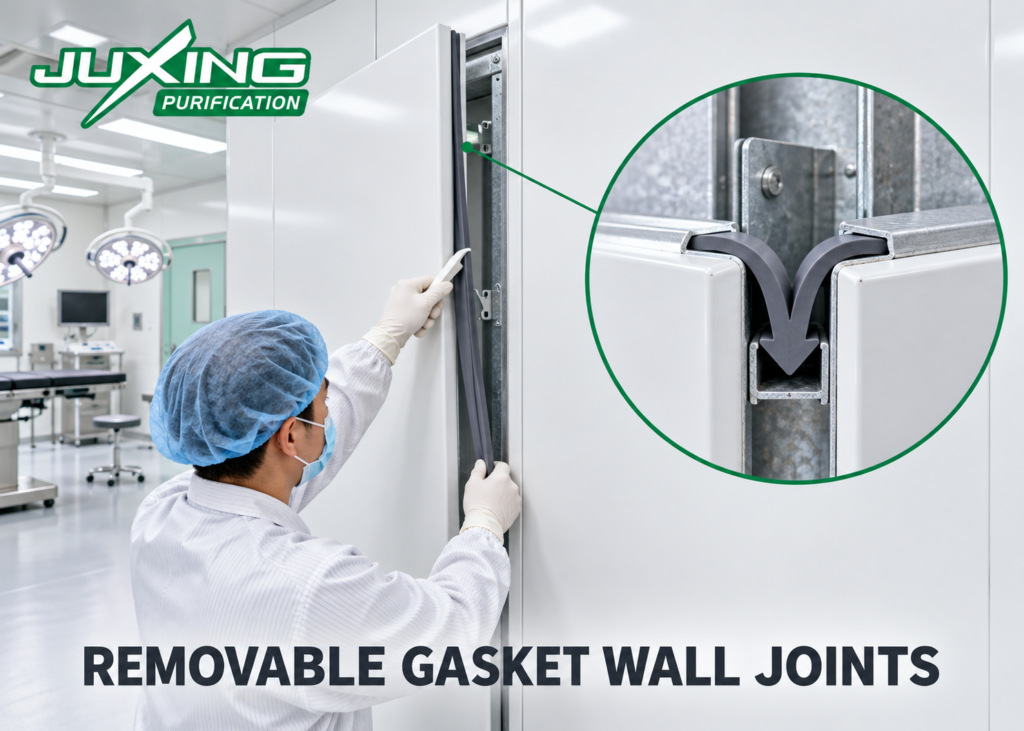
The joints between modular operating theater wall panels are critical parts of the room envelope. Although each panel may have a smooth and hygienic surface, poor joint design can create air-leakage paths, dirt traps and long-term maintenance problems.
Traditional modular wall systems commonly use wet-applied sealant between adjacent panels. This method can provide a smooth and airtight joint when correctly installed, but removing a panel usually requires cutting away the sealant and applying new material during reinstallation.
A removable gasket joint uses a mechanically retained sealing strip instead. The gasket fits into a purpose-designed groove between adjacent wall panels and is compressed by the panel connection. It can potentially be removed and replaced without cutting sealant, dismantling the complete wall or performing hot work inside the clinical area.
However, a gasket system is not automatically airtight simply because the strip fits tightly into a groove. Reliable performance depends on the gasket profile, material, compression, groove geometry, panel tolerances, corner details and installation quality.
Quick Answer
A removable gasket joint can provide a cleanable and maintainable connection between modular operating theater wall panels when the gasket and panel profiles are engineered as a complete system.
The gasket should be:
- Mechanically retained in a controlled groove
- Continuously compressed along the panel joint
- Compatible with hospital cleaning chemicals
- Resistant to compression set and ageing
- Removable without damaging the wall panels
- Replaceable using a documented maintenance procedure
An 11.2 mm gasket groove may be used in a particular proprietary or project-specific design, but it is not a universal international standard. The correct groove dimensions must be developed around the actual gasket profile, manufacturing tolerances and required compression.
ISO 14644 and healthcare ventilation guidance focus on the performance of the completed controlled environment. They do not prescribe a specific removable gasket, groove width or wall-panel connection.
Key Takeaways
- Removable gaskets can simplify future wall-panel replacement and service access.
- The gasket profile and retaining groove must be designed together.
- The gasket requires controlled compression to create a reliable seal.
- Excessive compression can damage the gasket and make removal difficult.
- Insufficient compression can create discontinuous leakage paths.
- An 11.2 mm groove is a design value—not a universal operating theater requirement.
- Corners, intersections and equipment penetrations are more difficult to seal than straight joints.
- “No sealant” should only be claimed if every interface has a validated mechanical sealing detail.
- Gasket materials must be compatible with disinfectants and fire requirements.
- Airtightness must be verified after installation and again after representative panel removal and refitting.
What Is a Removable Gasket Wall Joint?
A removable gasket wall joint is a dry mechanical connection between adjacent modular wall panels.
The joint normally consists of:
- Two formed panel edges
- A central groove or retaining channel
- A flexible gasket profile
- A concealed supporting frame
- A mechanical panel-locking or compression mechanism
- End, corner and intersection details
The gasket may include a barbed, arrow-shaped, T-shaped or dovetail-shaped retaining foot. This foot engages with the concealed groove and prevents the gasket from falling out during normal use.
The exposed portion of the gasket closes the visible joint between the wall panels. Depending on the profile, it may use one or more flexible lips, a hollow bulb or another compressible geometry to maintain contact with both panel edges.
When maintenance is required, the gasket may be pulled from the groove, allowing the associated wall panel to be released from its concealed fixings.
How Is It Different from a Sealant Joint?
A sealant joint and a gasket joint use different sealing principles.
| Feature | Wet-applied sealant joint | Removable gasket joint |
|---|---|---|
| Sealing method | Sealant bonds to both panel edges | Flexible profile is mechanically retained and compressed |
| Installation | Applied and finished on site | Gasket inserted after panel alignment |
| Curing time | Usually required | Normally no curing time |
| Panel removal | Sealant must be cut | Gasket can potentially be removed |
| Reinstallation | New sealant normally required | Existing or replacement gasket can be installed |
| Surface consistency | Depends on applicator skill | Controlled by the extruded gasket profile |
| Joint movement | Depends on sealant elasticity and adhesion | Accommodated by gasket deformation |
| Maintenance cleanliness | Cutting may produce debris | Dry extraction can reduce debris |
| Repair method | Remove and reapply sealant | Replace damaged gasket section |
| Main risks | Poor adhesion, irregular finish and curing defects | Incorrect compression, shrinkage or profile disengagement |
Neither method is inherently airtight under all conditions. Both require proper design, installation and inspection.
Sealant remains useful at certain irregular interfaces and penetrations, even when removable gaskets are used between the main wall panels.
What Does “Fully Dry Joint” Actually Mean?
A fully dry joint uses mechanical profiles and gaskets without wet-applied sealant along the standard panel-to-panel connection.
This can provide several practical benefits:
- No sealant curing period
- Less dependence on manual sealant finishing
- Easier replacement of individual panels
- Reduced debris during maintenance
- More repeatable visible joint dimensions
- Faster restoration of the room after minor repairs
However, describing an entire operating theater as a “sealant-free system” requires caution.
Even if straight wall-panel joints use removable gaskets, sealant or another supplementary sealing method may still be required around:
- Medical gas terminal boxes
- Electrical boxes
- Door frames
- Observation windows
- Return-air grilles
- Wall-to-floor transitions
- Wall-to-ceiling transitions
- Pipe and cable penetrations
- Irregular corners
- Structural movement joints
The correct claim is therefore often that the system uses dry removable gaskets at standard panel joints, rather than claiming that no sealant is used anywhere in the operating theater.
How Does the Gasket Create an Airtight Joint?
The gasket creates a seal by maintaining continuous contact pressure against the adjacent panel edges or sealing surfaces.
Three design elements are particularly important.
Retention
The gasket must remain securely engaged in its groove. A retaining foot prevents accidental displacement during cleaning, room pressurization and normal building movement.
The foot should not be so tight that the gasket tears during replacement.
Compression
The sealing lips or hollow bulb must be compressed within their intended working range.
If compression is too low:
- The sealing lips may not contact both panel edges.
- Small dimensional variations can create leakage paths.
- The gasket may become loose.
- The visible joint may appear uneven.
If compression is too high:
- The gasket may deform permanently.
- Removal force may become excessive.
- Panel edges may distort.
- The gasket may buckle or roll.
- Compression set may develop more quickly.
The acceptable compression should be defined by the gasket designer or material supplier. A nominal percentage should not be copied from an unrelated gasket profile.
Continuity
The seal must continue along the complete joint and through its interfaces.
Even a well-compressed straight gasket cannot provide room-envelope airtightness if leakage remains at its top, bottom or intersections.
Is an 11.2 mm Gasket Groove an International Standard?
No. An 11.2 mm groove may be appropriate for a particular wall-panel and gasket combination, but ISO 14644 and healthcare ventilation guidance do not establish 11.2 mm as a standard groove width.
The groove dimension should be determined by:
- Width of the gasket retaining foot
- Required insertion and extraction force
- Gasket material hardness
- Extrusion tolerances
- Sheet-metal forming tolerances
- Surface-coating thickness
- Panel installation tolerances
- Expected thermal movement
- Required sealing compression
- Method of lateral or front extraction
For example, a nominal 11.2 mm dimension must be accompanied by defined tolerances. A groove described only as “11.2 mm” is incomplete if the acceptable upper and lower limits are not stated.
The drawing should distinguish between:
- Groove entrance width
- Internal retaining width
- Groove depth
- Sealing-face spacing
- Panel-to-panel visible joint
- Gasket foot dimensions
- Gasket exposed-face dimensions
A prototype should be produced before the groove dimension is released for full-scale wall-panel production.
Which Gasket Materials Are Suitable?
Several elastomeric materials can be considered, but the final choice should be based on documented performance.
EPDM
EPDM is widely used for architectural and equipment seals because it can provide good resistance to ageing, water and many cleaning solutions.
Potential advantages include:
- Good elastic recovery
- Resistance to ozone and environmental ageing
- Availability in different hardness grades
- Suitability for continuous extrusion
Its compatibility with the hospital’s actual disinfectants must still be verified.
Silicone Rubber
Silicone can retain flexibility across a wide temperature range and can offer good ageing performance.
Potential advantages include:
- Good flexibility
- Availability in light colors
- Good temperature resistance
- Potential for high-quality hygienic profiles
Depending on formulation, silicone may have lower tear resistance than some other elastomers. Extraction forces and retaining-foot design therefore require careful control.
Thermoplastic Elastomer
TPE materials can be extruded efficiently and may allow profiles with different hardness zones.
Potential advantages include:
- Flexible manufacturing
- Possibility of co-extruded rigid and soft sections
- Consistent profile geometry
- Potential recyclability, depending on formulation
Chemical resistance, compression set and long-term ageing vary considerably between TPE grades.
PVC-Based Flexible Profiles
Flexible PVC may be economical and easy to extrude, but plasticizer migration, ageing, chemical resistance and long-term flexibility must be evaluated carefully.
The material should not be selected based only on initial softness or price.
Which Material Properties Should Be Specified?
A gasket specification should consider:
- Material family and formulation
- Shore hardness
- Tensile strength
- Elongation
- Tear resistance
- Compression set
- Dimensional stability
- Chemical resistance
- Ageing resistance
- Cleaning-agent compatibility
- Color stability
- Surface finish
- Fire and smoke requirements
- Expected service life
- Manufacturing tolerance
General claims such as “medical-grade rubber” or “antibacterial gasket” are insufficient unless the supplier can define the material and supporting test method.
Antimicrobial additives should not be used as a substitute for cleanable joint design and routine environmental cleaning.
Should the Gasket Be Pulled Out from the Front or the Side?
Both removal concepts are possible, but they require different gasket and groove designs.
Front-Removable Gasket
A front-removable gasket is pulled directly out from the visible joint.
Advantages may include:
- Access from any point along the joint
- Easier replacement of a damaged section
- No need for a clear extraction path at the end
Possible limitations include:
- Higher risk of accidental disengagement
- Visible tool access requirements
- Potential damage to panel coatings
- More demanding retention-profile design
Laterally Extracted Gasket
A laterally extracted gasket is pulled along the length of the groove after its end becomes accessible.
Advantages may include:
- Strong mechanical retention
- Low risk of accidental front disengagement
- Clean and narrow visible joint
- Continuous gasket installation
Possible limitations include:
- Requires an accessible extraction end
- Long gasket strips may create high friction
- Corners and intersecting equipment can block removal
- A complete room-height strip may be difficult to pull manually
- Replacement may be complicated if the groove is not accurately aligned
A system described as “laterally removable” must show where the technician begins extraction and how sufficient working space is created.
Can One Continuous Gasket Be Used from Floor to Ceiling?
It is technically possible, but it is not always the most practical maintenance solution.
A full-height gasket offers fewer intermediate joints. However, its extraction force increases with length, and it may be obstructed by:
- Horizontal wall-panel divisions
- Control panels
- Built-in cabinets
- Handrails
- Medical equipment rails
- Ceiling coving
- Floor coving
- Intermediate fixing profiles
Where operating theater walls use three horizontal panel sections, the gasket system should define whether the vertical gasket:
- Passes continuously through all three sections
- Is divided at horizontal joints
- Uses separate removable segments
- Terminates at purpose-designed intersection blocks
Shorter replaceable gasket sections can simplify maintenance, but each additional termination introduces another potential leakage point.
How Should Horizontal and Vertical Joints Intersect?
Cross-joints and T-joints are more difficult to seal than straight panel joints.
At an intersection, the design must prevent:
- One gasket interrupting the compression of another
- Open cavities behind the visible joint
- Raised or overlapping gasket edges
- Dirt-trapping recesses
- Excessive local panel deformation
Possible solutions include:
- Factory-cut gasket intersections
- Molded intersection pieces
- Mechanically compressed junction blocks
- Overlapping lip geometries
- Continuous primary gasket with a secondary joint terminating against it
The selected detail should be tested in a full-size mock-up. A two-dimensional drawing alone may not reveal local gaps at the center of the intersection.
How Are Internal and External Corners Sealed?
Operating theater corners should be smooth, cleanable and resistant to repeated impact and cleaning.
Common corner arrangements include:
- Curved aluminum internal-corner profiles
- Formed stainless steel or coated-steel corners
- Flexible hygienic corner strips
- Prefabricated corner modules
- Mechanically connected corner coving
For a removable gasket system, the corner detail must also establish:
- Where the straight gasket terminates
- How the termination is compressed
- Whether the corner can be removed independently
- How the replacement gasket is inserted
- Whether supplementary sealant is required
- How the floor and ceiling seals connect to the corner
A nominally removable straight gasket does not eliminate the need to design its corner termination.
How Does Mechanical Panel Compression Work?
The gasket should not be expected to correct a loosely installed wall panel.
The wall panels normally require a concealed fixing or compression system that pulls the panel edges into their intended positions. Possible mechanisms include:
- Rear clamping plates
- Adjustable hooks
- Cam-lock connectors
- Bolted backing profiles
- Spring clips
- Concealed retaining rails
The mechanism should maintain:
- Correct panel alignment
- Consistent joint width
- Controlled gasket compression
- Resistance to accidental panel movement
- Access for future release
- Sufficient capacity for the panel weight
The gasket seals the joint; it should not be used as the main structural connection between panels.
The supporting structure and panel options are compared in Operating Theater Wall Panels: Steel vs Sandwich.
Can the Wall Panel Be Removed Without Damaging Adjacent Panels?
Yes, if the wall system is designed for independent removal.
A typical removal sequence may be:
- Isolate and make safe any services connected to the panel.
- Remove the relevant gasket strip or strips.
- Release the concealed rear compression or retaining mechanism.
- Disconnect terminal boxes and service modules where applicable.
- Pull the panel forward using approved suction tools or handling devices.
- Protect adjacent panel edges and exposed services.
- Complete the inspection or repair.
- Reinstall and align the wall panel.
- Fit a new or verified reusable gasket.
- Inspect and test the restored joint.
The installation manual should identify which panels are genuinely removable. Panels containing fixed pipework, large cabinets or complex medical services may require additional disconnection procedures.
Can the Existing Gasket Be Reused?
Possible reuse depends on the gasket condition, system design and project maintenance policy.
A gasket should normally be replaced if it shows:
- Permanent flattening
- Loss of elasticity
- Surface cracking
- Cuts or tears
- Chemical swelling
- Hardening
- Shrinkage
- Discoloration associated with material deterioration
- Damage to the retaining foot
- Contamination that cannot be removed
Reusing a gasket merely because it can still be inserted into the groove is not sufficient.
For critical projects, the maintenance procedure may require a new gasket whenever a panel is removed. This provides more predictable sealing but increases spare-parts requirements.
How Should Medical Services Be Coordinated?
Removable wall panels often contain electrical, medical gas and communication services. Panel removability therefore depends on more than the gasket.
The design should coordinate:
- Flexible cable lengths
- Plug-and-socket electrical connections
- Medical gas isolation requirements
- Terminal-box mounting
- Equipotential bonding
- Data and communication cables
- Access to connection points
- Identification of concealed services
- Safe disconnection procedures
Whenever possible, permanent services should be supported independently from the removable facing panel.
The panel should not be removed until medical gas, electrical and communication systems have been safely isolated by qualified personnel.
Additional guidance is provided in Medical Gas and Electrical Services Integration for Operating Theaters.
How Do Removable Gaskets Affect Room Airtightness?
A properly designed gasket system can help limit leakage through panel joints. However, the room’s pressure performance depends on the complete envelope and ventilation system.
Other leakage paths include:
- Hermetic door perimeters
- Door undercuts
- Observation windows
- Ceiling panels
- Light fixtures
- Medical pendants
- Terminal HEPA housings
- Return-air grilles
- Pipe penetrations
- Electrical conduits
- Wall-to-floor junctions
Room pressure is created by maintaining the required relationship between supply, return, exhaust and uncontrolled leakage airflow.
The gasket does not create positive pressure by itself. It helps the ventilation system maintain the required pressure by reducing uncontrolled leakage.
This relationship is explained further in the Operating Theater Positive Pressure Guide.
Do ISO 14644 and HTM 03-01 Require Removable Gaskets?
No. These documents do not prescribe an 11.2 mm groove, a particular gasket material or a removable wall-joint system.
ISO 14644-4:2022 establishes a structured process for specifying, designing, constructing and starting up cleanroom installations. It applies to new, refurbished and modified facilities but does not prescribe one specific construction technology.
HTM 03-01 Part A provides guidance on the design and validation of specialized healthcare ventilation systems. The wall envelope affects leakage and pressure control, but HTM 03-01 does not approve a particular proprietary gasket profile.
Therefore, an accurate technical statement would be:
The removable gasket wall system is designed to support cleanability, maintainability and room-envelope airtightness. Final compliance depends on the complete project design, installation quality and specified verification tests.
It would be inaccurate to state that a gasket system automatically “complies with ISO 14644 and HTM 03-01” solely because it uses removable joints.
How Should the Gasket System Be Prototyped?
A full-size prototype should be manufactured before mass production.
The prototype should include:
- Two or more wall panels
- The actual supporting frame
- Vertical gasket joints
- A horizontal joint
- A cross-joint or T-joint
- An internal corner
- A representative service box
- Floor and ceiling terminations
- Concealed panel-release hardware
The prototype should be used to evaluate:
- Panel alignment
- Visible joint width
- Gasket insertion force
- Gasket extraction force
- Continuous compression
- Panel-release procedure
- Surface damage during removal
- Ease of reinstallation
- Cleaning performance
- Local leakage paths
The same gasket should be removed and reinstalled through representative maintenance cycles to reveal possible wear, stretching or retaining-foot damage.
What Manufacturing Tolerances Are Important?
Removable gasket systems require more precise manufacturing than joints that rely on a thick bead of wet sealant.
Important tolerances include:
- Folded panel-edge dimensions
- Groove entrance width
- Groove depth
- Gasket-profile dimensions
- Panel height and width
- Frame straightness
- Panel-edge parallelism
- Coating thickness
- Joint alignment
- Fixing position
Tolerance accumulation must be evaluated across the complete wall.
For example, small deviations in two adjacent panel folds, the supporting frame and gasket extrusion can combine to produce excessive or insufficient compression.
Inspection gauges can be created for:
- Gasket-profile dimensions
- Groove dimensions
- Joint width
- Panel-edge geometry
- Installed gasket position
How Should the Joint Be Tested?
Testing should be divided into component, mock-up and completed-room stages.
Component Inspection
Verify:
- Gasket dimensions
- Material hardness
- Surface finish
- Retaining-foot geometry
- Groove dimensions
- Material documentation
- Chemical compatibility
Mock-Up Testing
Assess:
- Gasket insertion and removal
- Panel removal and reinstallation
- Joint alignment
- Leakage at straight joints
- Leakage at intersections
- Corner continuity
- Repeatability after maintenance cycles
Completed-Room Verification
The final operating theater should be tested according to the project’s commissioning and validation plan.
Relevant checks may include:
- Visual inspection
- Room pressure differential
- Pressure stability
- Airflow balance
- Local smoke visualization
- Investigation of suspected leakage paths
- Inspection after panel removal and refitting
A room-pressure reading alone does not prove that every wall joint is airtight. The ventilation system may compensate for significant leakage by supplying more air.
Similarly, a locally tight gasket does not prove that the complete room envelope meets the project requirements.
How Should the Gaskets Be Cleaned?
The exposed gasket surface should be smooth and accessible for routine cleaning.
The manufacturer should provide instructions covering:
- Approved cleaning agents
- Maximum chemical concentration
- Required dilution
- Contact time
- Wiping method
- Rinsing requirements
- Inspection frequency
- Prohibited solvents or abrasive tools
Cleaning staff should not use sharp tools to remove contamination from the gasket joint.
Repeated exposure to unsuitable chemicals can cause:
- Swelling
- Hardening
- Softening
- Surface tackiness
- Discoloration
- Cracking
- Loss of elastic recovery
Material compatibility should be evaluated using the facility’s actual cleaning products rather than a generic claim of chemical resistance.
How Should Maintenance Be Planned?
The facility should keep an appropriate stock of:
- Replacement gasket rolls
- Prefabricated corner pieces
- Intersection pieces
- Gasket extraction tools
- Installation rollers
- Approved cleaning materials
- Panel suction tools
- Replacement clips and fasteners
- Touch-up coating materials
Spare gaskets should be stored according to the material supplier’s recommendations and protected from:
- Direct sunlight
- Excessive heat
- Ozone-generating equipment
- Oils and solvents
- Dust
- Mechanical deformation
The maintenance manual should identify each gasket profile and installation location. Similar-looking profiles should not be mixed unless interchangeability has been verified.
What Are the Main Failure Modes?
Gasket Shrinkage
Some gasket materials may contract after extrusion, installation or long-term ageing. Shrinkage can create gaps at the top, bottom or intersections.
Compression Set
The gasket can gradually lose its ability to recover after prolonged compression. This reduces contact pressure when panels move slightly.
Retaining-Foot Damage
Excessive extraction force or an incorrectly shaped groove can tear the gasket foot.
Panel Misalignment
A gasket cannot reliably seal panels that are twisted, uneven or installed at inconsistent spacing.
Chemical Degradation
Incompatible disinfectants can change the gasket’s dimensions, hardness or surface condition.
Corner Leakage
Straight joints may perform correctly while corner and termination details remain open.
Uncontrolled Field Cutting
Incorrectly shortened gaskets can leave gaps. Overlength gaskets can buckle or create raised sections.
Incomplete Reinstallation
After maintenance, the gasket may appear correctly installed at the surface while part of its retaining foot remains outside the groove.
Buyer’s Checklist
Before approving a removable gasket joint system, ask:
- What is the gasket material?
- What is its Shore hardness?
- Is the complete gasket profile drawing available?
- What are the groove width, depth and tolerances?
- Is the stated 11.2 mm dimension nominal or controlled?
- How is gasket compression created?
- What compression range is recommended?
- How is the gasket mechanically retained?
- Is it removed from the front or extracted laterally?
- Where does lateral extraction begin?
- What is the maximum practical gasket length?
- How are horizontal and vertical joints connected?
- How are internal and external corners sealed?
- How does the gasket terminate at the floor and ceiling?
- Are molded or fabricated intersection pieces required?
- Which interfaces still require sealant?
- Can one wall panel be removed independently?
- How are services disconnected before panel removal?
- Can the gasket be reused?
- How many removal cycles have been evaluated?
- Which disinfectants are compatible with the material?
- What fire and smoke requirements apply?
- What dimensional inspections are performed during production?
- Will a full-size mock-up be produced?
- How will airtightness be verified?
- Are spare gaskets and installation tools included?
Common Misconceptions
“A removable gasket is automatically airtight.”
Incorrect. Airtightness depends on gasket compression, joint continuity, panel alignment and interface details.
“An 11.2 mm groove is required by European standards.”
Incorrect. This is a system-specific design dimension rather than a universal European or international requirement.
“No sealant is needed anywhere in the operating theater.”
Not necessarily. Standard panel joints may use dry gaskets, while irregular penetrations and perimeter interfaces may still require sealant or specialized sealing components.
“The gasket holds the wall panels together.”
The primary panel connection should be mechanical and structural. The gasket seals the joint but should not serve as the principal wall-panel fixing.
“A gasket can always be reused after panel removal.”
Not necessarily. A gasket showing damage, deformation or loss of elasticity should be replaced.
“Passing the room-pressure test proves that every joint is airtight.”
Incorrect. The ventilation system may maintain pressure despite excessive leakage by delivering additional air.
“ISO 14644 approves this gasket design.”
ISO 14644 does not approve specific manufacturers, gasket profiles or groove dimensions.
Expert Tip
Do not begin by designing the steel-panel groove and then searching for a gasket that happens to fit it.
Select or develop the gasket profile first. Determine its sealing surfaces, retaining-foot geometry, recommended compression and manufacturing tolerances. The steel-panel folds and supporting mechanism can then be designed around the actual gasket.
The preferred development sequence is:
- Define the required panel-removal method.
- Select the gasket material.
- Develop the gasket cross-section.
- Establish the working compression range.
- Design the panel-edge groove.
- Calculate the complete tolerance stack.
- Manufacture a short test sample.
- Produce a full-size wall mock-up.
- Test removal and reinstallation.
- Finalize production drawings and inspection gauges.
This sequence reduces the risk of investing in wall-panel tooling that cannot reliably retain or compress the selected gasket.
Frequently Asked Questions
Can a removable gasket joint be used with three-section wall panels?
Yes. However, the horizontal and vertical gasket intersections must be carefully designed. The system should define whether the vertical gasket is continuous or divided into independently replaceable sections.
Is EPDM better than silicone?
Neither material is universally better. EPDM may provide good mechanical durability and resistance to many cleaning solutions, while silicone may provide excellent flexibility and temperature stability. The actual material grade should be evaluated against the project requirements.
Can the gasket be manufactured locally?
Yes, if a capable extrusion manufacturer can control material formulation, cross-sectional dimensions, hardness and surface quality. A custom extrusion die will normally be required for a proprietary profile.
Does a custom gasket require expensive tooling?
Extrusion tooling is generally simpler than tooling for large metal components, but cost depends on profile complexity, material and supplier. Prototype tooling may be used before committing to production tooling.
Can the gasket be installed without adhesive?
Yes, if its retaining foot and groove provide sufficient mechanical retention. Adhesive-free installation should be confirmed through mock-up testing and repeated removal cycles.
Can one person replace the gasket?
Short straight sections may be manageable by one trained technician. Long laterally extracted gaskets, corner sections and panel removal may require two people.
Should the gasket be flush with the panel surface?
The exposed face should be smooth and cleanable. Whether it is exactly flush, slightly recessed or slightly proud depends on the designed profile. It should not create a significant dirt trap or interfere with cleaning.
How often should the gasket be replaced?
There is no universal replacement interval. Inspection should consider loss of elasticity, surface damage, shrinkage, chemical degradation and maintenance history.
Can the gasket compensate for uneven wall panels?
Only within a limited designed range. Significant panel misalignment should be corrected through the supporting frame and panel-fixing system.
Is a removable gasket system suitable for international projects?
Yes, provided it meets the project’s requirements for materials, cleanability, fire performance, maintainability and verified room-envelope performance. Acceptance depends on the complete technical submission and installed results.
Conclusion
A removable gasket joint can improve the maintainability of modular operating theater walls by allowing selected panels to be removed and reinstalled without cutting and replacing the entire visible joint seal.
Its success depends on much more than fitting a rubber strip into a metal groove.
The gasket material, retaining foot, sealing lips, groove geometry, mechanical compression, panel tolerances, intersections, corners and service interfaces must be developed as one coordinated system.
An 11.2 mm gasket groove may be suitable for a specific wall construction, but it is not a universal standard. Its dimensions and tolerances should be confirmed through gasket development, sample testing and a full-size mock-up.
Most importantly, the system should be described accurately. Removable dry gaskets can support cleanability, airtightness and maintenance, but compliance with cleanroom and healthcare requirements must be demonstrated through the complete project design, installation and verification process.